AutoCAD Dimensions
It is used to display the dimensions of drawings or models in AutoCAD. We can modify the dimensions in different drawing units according to the requirements.
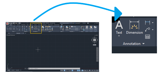
The dimension area on the ribbon panel will look like the below image:
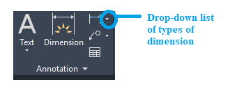
There are different types of dimensions. It will appear on the drop-down list of the dimension, as shown in the below image:
The drop-down list will look like the below image:
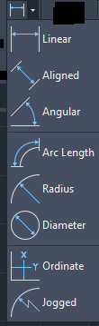
We can choose the desired dimension accordingly.
Let’s discuss each type of dimension in detail.
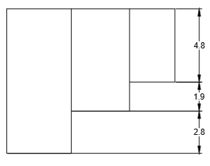
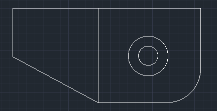
Here, we will consider the below image:
- Linear Dimension
A linear dimension will give us the horizontal or vertical distance between the selected points.
Let’s measure the linear dimensions of the above figure.
The steps are listed below:- Select the Linear icon from the ribbon panel.
Or
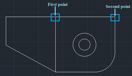
Type DLI or DIMLINEAR on the command line and press Enter. - Select the first point and second point of a line to be measured, as shown below:

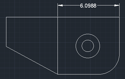
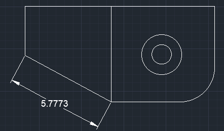
- The dimension of the corresponding line will be displayed, as shown below:
- Select the Linear icon from the ribbon panel.
- Aligned Dimension
The aligned dimension will give us the exact distance between the two selected points or endpoints. It is commonly used to measure the slanted lines.
The dimensions will be parallel to the created slanted line.
Let’s measure the aligned dimensions of the above figure.
The steps are listed below:- Select the Aligned icon from the ribbon panel.
Or
Type DAL or DIMALIGNED on the command line and press Enter. - Select the first point and second point of a line to be measured, as shown below:
- The dimension of the corresponding line will be displayed, as shown below:
- Select the Aligned icon from the ribbon panel.
What is the difference between linear and aligned dimensions?
The aligned dimension displays the true or exact value of the slanted lines, while the linear dimension does not.
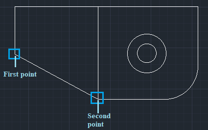
Let’s consider a figure. The two points of a slanted line are shown in the below image:

The value of the linear and aligned dimensions are shown in the below image:
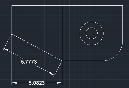
We can consider that aligned dimensions are parallel to the line while linear is not. We can also notice the difference between the two values.
Hence, for slanted lines, aligned dimensions are recommended.
- Angular Dimension
The angular dimensions will give us the measurement of the angle between the two selected lines.
Let’s measure the angular dimensions of the above figure.
The steps are listed below:- Select the Angular icon from the ribbon panel.
Or
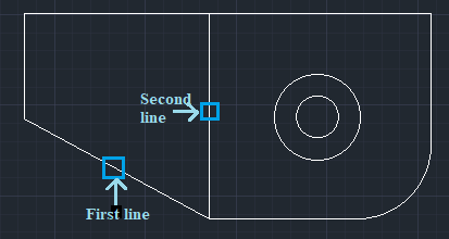
Type DIMANG or DIMANGULAR on the command line and press Enter. - Select the first line and second line in the given figure, as shown below:
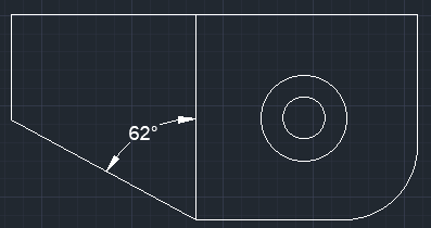
- The value of the angle between the two selected lines will be displayed, as shown in the below image:
- Select the Angular icon from the ribbon panel.
- Arc Length Dimension
The arc dimension measures the distance along an arc or polyline arc segment. The symbol of the arc is displayed either above or before the dimension value.
Let’s measure the Arc Length dimensions of the arc in the above figure.
The steps are listed below:- Select the Arc Length icon from the ribbon panel.
Or
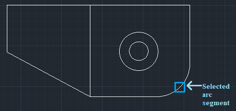
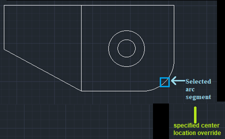
Type DAR or DIMARC on the command line and press Enter. - Select the arc or polyline arc segment in the figure. Here, we have selected the polyline arc segment because the arc is joined to the lines.
The selected arc is shown in the below image:
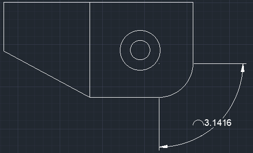
- The value of the arc chosen will be displayed, as shown in the below image:
- Select the Arc Length icon from the ribbon panel.
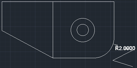
- Radius Dimension
The radius dimension will measure the radius of the selected circle or arc. It displays the radius symbol before the dimensioning text.
Let’s measure the Radius dimensions of the circle in the above figure.
The steps are listed below:- Select the Radius icon from the ribbon panel.
Or
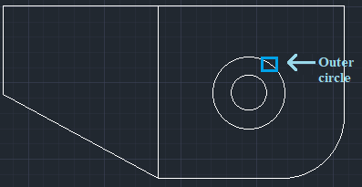
Type DIMRAD or DIMRADIUS on the command line and press Enter. - Select the circle. Here, we have selected the outer circle, as shown in the below image:
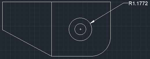
- The radius of the selected circle will be displayed, as shown in the below image:
- Select the Radius icon from the ribbon panel.
- Diameter Dimension
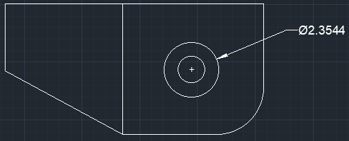
The diameter dimension will give us the diameter of the selected circle.
Note: The diameter dimensions are popularly used to measure the diameter of the circle, while the radius dimensions are used to determine the radius of an arc or fillet.
It displays the diameter symbol before the dimensioning text.
Let’s measure the Diameter dimensions of the circle in the above figure.
The steps are listed below:
- Select the Diameter icon from the ribbon panel.
Or
Type DIMDIA or DIMDIAMETER on the command line and press Enter. - Select the circle. Here, we have selected the outer circle, as shown in the below image:
- The diameter of the selected circle will be displayed, as shown in the below image:
We can move the cursor in any direction to place the dimensions.

- Ordinate Dimension
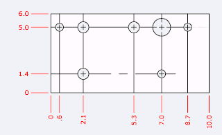
The ordinate dimension measures the horizontal or vertical distance from the point of origin.
For example, consider the below image:
Here, we need to specify the feature location or center point in the figure. The Ordinate dimension will display the ordinate value of the specified feature point. - Jogged Dimension
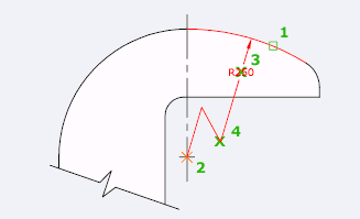
It is used to create jogged radius dimensions. The dimensions are created when the center of the circle or arc is located off the layout.
For example, consider the below image:
Lets measure the Jogged dimensions of the arc in the above figure.
The steps are listed below:- Select the Jogged icon from the ribbon panel.
Or
Type DIMJOGGED on the command line and press Enter. - Select the arc or circle. Here, we have selected the arc, as shown in the below image:
- Specify the center location override. It is the distance between the arc and jogged starting point, as shown in above image.
The jogged radius of the selected arc will be displayed, as shown in the below image:
- Select the Jogged icon from the ribbon panel.
Quick Dimension
The Quick dimension command is used to create dimensions from the selected objects quickly.
Let’s understand with an example.
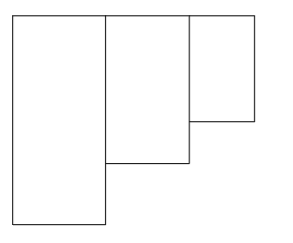
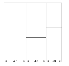
Consider the below figure:
The steps are listed below:
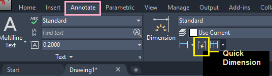
- Select Annotate tab>Quick Dimension, as shown in the below image:
Or
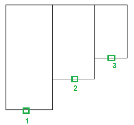
Type QD or QDIM on the command liner and press Enter. - Select the geometry to dimension.
We can select any part of the object.
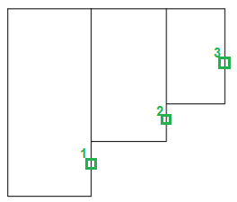
Here, we have selected the three horizontal lines of the figure, as shown in the below image:
- Press Enter.
- Place the dimension to the desired position.
Here, we will place at the bottom, as shown in the below image:
If we will select the vertical lines, as shown below:
The dimensions will be displayed, as shown below: