AutoCAD Loft
The loft command in AutoCAD is used to create 3D solid or surface. The 3D solid or surface is formed within the space between various cross sections.
The cross-sections determine the outer shape of the solid or surface.
To create a 3D object using LOFT, we are required to specify at least two cross-sections.
The cross-sections and objects of Loft command can be:
- Planar
- Non-planar
- Open
- Closed
- Edge sub-objects
- Solid
- Surfaces
- Polyline
- Arc
- Circle
- Ellipse
- Line
- Helix
- Region
- Trace
- Ellipse
- Elliptical arc
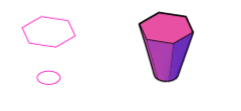
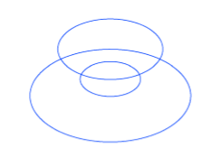
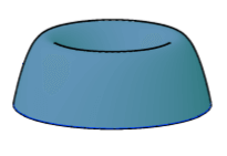
Consider the below image:
Let’s understand with two examples.
Example 1:
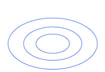
Consider the below image:
The above drawing is created in SE Isometric.
We can also change the View control accordingly.
The steps are listed below:
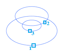
1. Create the three circles, as shown above.
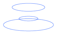
2. Move the circles separately in the direction of Z-axis using the MOVE command, as shown below:
Another view is:
3. Select the LOFT icon from the ribbon panel, as shown below:
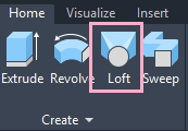
Or
Type Loft on the command line < press Enter.
4. Select the cross-section (circles) to apply loft, as shown below:
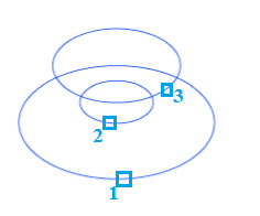
The order is shown above.
5. Press Enter.
The loft will be created, as shown below:
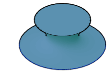
Another view is:
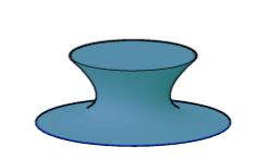
Let’s change the order of the lofting, as shown below:
The object will now look like:
Another view is:
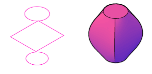
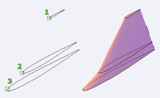
Example 2:
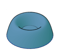
Here, we are showing some figures before and after the loft.