AutoCAD Units
The units are used to represent the dimensions in AutoCAD. The units are categorized into length, angle, insertion scale, and lighting.
We can change the units according to the requirements.
We can access the units in AutoCAD using two ways, as discussed below:
1. First way:
The steps for the first method are listed below:
- Click on the Application Menu button, which will look like the given image:

- Select the Drawing Utilities and then select Units.
- The dialog box of units will appear on the screen.

2. Second way:
The steps for the second method are listed below:
- Type Units or UN on the command line or command prompt.
- Press Enter or Spacebar.
- The dialog box of units will appear on the screen.
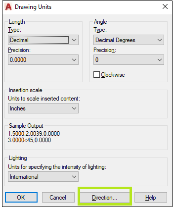
The Units dialog box will look like the below image:
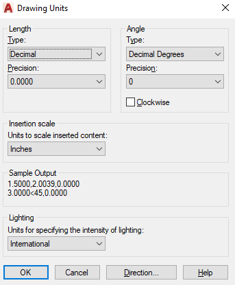
Let’s discuss the Units dialog box in detail.
Length Type
The drop-down list under Length type will look like the below image:
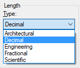
- Architectural Units
The architectural units are based on the feet and inches. It uses fractions to represents the partial inches. It displays feet and inches in the format of decimals and fractions. For example, 4′- 5 1/2″.
Here, single quotes (‘) signifies feet and double quotes (“) signifies inches. - Decimal Units
The decimal units can be represented as an inch, meter, millimeter, or any other unit. - Engineering Units
The engineering units are like architectural units, but they represent the feet and inches in the format of the decimal. For example, 4’5.5000″. - Fractional Units
The fractional units are the unitless decimal units, which display the value in fractions rather than decimals. For example, 5/2.
It also represents whole numbers or whole numbers with fractions. For example, 5 ½. - Scientific Units
The scientific units are used to display the units in the form of the decimal value raised to a power. It displays the value of exponents. For example, 2.600E + 04. It is used to display large values.
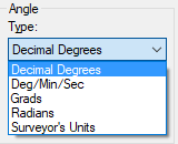
Angle Type
The angle type consists of the units such as radians, minutes, seconds, etc. We can select these units according to the requirements.
The drop-down list under angle type will look like the below image:
Let’s discuss each type in detail.
- Decimal Degrees
It displays the angle value in decimals. - Deg/Min/Sec
AutoCAD uses d for representing degree because there is no keyword for the degree on the keyboard of the computer. For example, 10d20’21”. Here, single quotes (‘) signifies minutes and double quotes (“) signifies seconds. - Grad and Radians
The Grads and Radians are the mathematical units.
Since Circumference = 2*pi*r.
So, in a full circle there are 2 pi radians.
1 radian = 63.66 grad = 57.3 degrees - Surveyor’s Units
The surveyor’s units are similar to the grad and radians but use quadrants instead of a full circle.
Angle Measure
To measure the angle clockwise, click on the clockwise box to activate it.
The option is present under the angle. It will look like the given image:
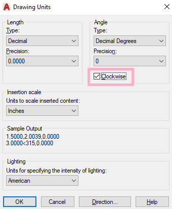
It measures the angle in the clockwise direction, instead of the counter-clockwise direction
Precision
The precision value in AutoCAD determines the number of decimal places displayed in the corresponding unit. The decimals are round off to the specified precision value.
The drop-down list under precision will look like the below image:
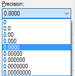
We can select the precision value according to the requirements.
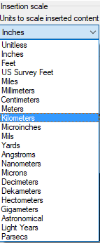
Insertion Scale
The insertion scale consists of the units to insert in the content. We can select the units from the drop-down list according to the requirements.
The drop-down list under Insertion Scale will look like the below image:
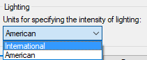
Lighting
It specifies the lighting units for the drawing. It enables generic or photometric lights.
When the lighting unit is set to American (also called as foot-notes) and international, it enables the photometric lighting.
The default or no lighting unit enables the standard (generic) lighting. It sets the value to 0 to maintain the backward compatibility.
We can also type LIGHTINGUNITS in the command line or command prompt to activate it.
The LIGHTINGUNITS value is set to 0 to activate the standard lighting.
The LIGHTINGUNITS value is set to 1 to activate the American lighting.
The LIGHTINGUNITS value is set to 2 to activate the International lighting.
The drop-down list under Lighting will look like the below image:
What is photometric lighting?
The photometric lighting uses light energy values, which gives a realistic and natural appearance to a scene. It defines lights more accurately as it would be in the real world.
Direction
The values for the directions are listed in the below table:
| Value | Direction |
|---|---|
| 0 | East |
| 90 | North |
| 180 | West |
| 270 | South |
| Other | Used to specify other angle value |
The steps to set the direction are given below:
- Type Units or UN on the command line or command prompt.
- Press Enter or Spacebar.The dialog box of units will appear on the screen.
- Click on the direction option at the bottom, as shown in the below image:
- A dialog box will appear, as shown in the below image:
- Under the Base Angle, enter 0 for the default angle direction. The default degree is 0 (East), and direction is counter-clockwise.
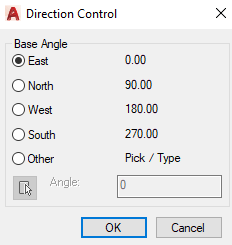
The angle change is required in drafting.
We can select and specify any angle according to the requirements.