Cellular System Infrastructure
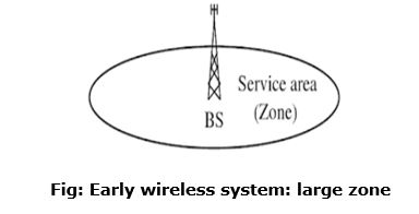
Early wireless systems had a high-power transmitter, covering the entire service area. This required a very huge amount of power and was not suitable for many practical reasons.
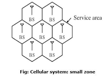
The cellular system replaced a large zone with a number of smaller hexagonal cells with a single BS (base station) covering a fraction of the area. Evolution of such a cellular system is shown in the given figures, with all wireless receivers located in a cell being served by a BS.
Wireless devices need to be supported for different types of services, the wireless device could be a wireless telephone laptop with wireless card, personal digital assistant (PDA), or web enabled phone. For simplicity, it could be called an MS.
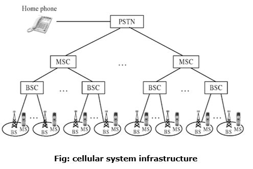
In a cellular structure, a MS (mobile station) needs to communicate with the BS of the cell where the MS is currently located and the BS acts as a gateway to the rest of the world. Therefore, to provide a link, the MS needs to be in the area of one of the cells (and hence a BS) so that mobility of the MS can be supported. Several base stations are connected through hard-wires and are controlled by a BS controller (BSC), which in turn is connected to a mobile switching center (MSC).
Several mobile switching centers are interconnected to a PSTN (public switched telephone network) and the ATM (asynchronous transfer mode) backbone. To provide a better perspective of wireless communication technology, simplified system infrastructure for cellular system is shown in the figure:
A cellular system requires a fairly complex infrastructure. A generic block diagram in shown in the figure:
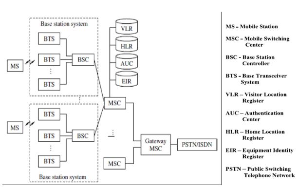
A BS consists of a base transceiver system (BTS) and a BSC. Both tower and antenna are a part of the BTS, while all associated electronics are contained in the BSC.
The HLR (home location register) and VLR (visitor location register) are two sets of pointers that support mobility and enable the use of the same telephone numbers worldwide.
The AUC (authentication center) unit provides authentication and encryption parameters that verify the user’s identity and ensure the confidentiality of each cell.
The EIR (equipment identity register) is a database that information about identity of mobile equipment. Both AUC and EIR can be implemented as individual stand-alone units or as a combined AUC/EIR unit.
The HLR is located at the MSC where MS is initially registered and is the initial home location for billing and access information.
In simple words, any incoming call, based on the calling number, is directed to the HLR of the home MS where the MS is registered. The HLR then points to the VLR of the MSC where the MS is currently located.
Bidirectional HLR-VLR pointers help in carrying out various functionalities, as illustrated in the figure:
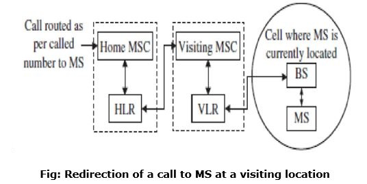
The VLR contains information about all MS visiting that particular MSC and hence points to the HLR of the visiting MSs for exchanging related information about the MS.
Such a pointer allows calls to be routed or rerouted to the MS, wherever it is located. In cellular systems, a reverse direction pointer is needed that allows traversal of many control signals back and forth between the HLR and VLR such bidirectional HLR-VLR pointers help in carrying out various functionalities.