Combinational Logic circuits
The combinational logic circuits are the circuits that contain different types of logic gates. Simply, a circuit in which different types of logic gates are combined is known as a combinational logic circuit. The output of the combinational circuit is determined from the present combination of inputs, regardless of the previous input. The input variables, logic gates, and output variables are the basic components of the combinational logic circuit. There are different types of combinational logic circuits, such as Adder, Subtractor, Decoder, Encoder, Multiplexer, and De-multiplexer.
There are the following characteristics of the combinational logic circuit:
- At any instant of time, the output of the combinational circuits depends only on the present input terminals.
- The combinational circuit doesn’t have any backup or previous memory. The present state of the circuit is not affected by the previous state of the input.
- The n number of inputs and m number of outputs are possible in combinational logic circuits.
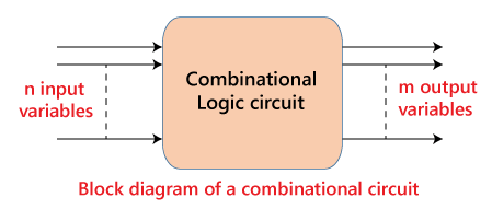
The ‘n’ input variable comes from the external source while the ‘m’ output variable goes to the external destination. In many applications, the source or destinations are storage registers.
Half Adder
The half adder is a basic building block having two inputs and two outputs. The adder is used to perform OR operation of two single bit binary numbers. The carry and sum are two output states of the half adder.
Full Adder
The half adder is used to add only two numbers. To overcome this problem, the full adder was developed. The full adder is used to add three 1-bit binary numbers A, B, and carry C. The full adder has three input states and two output states i.e., sum and carry.
Half Subtractors
The half subtractor is also a building block of subtracting two binary numbers. It has two inputs and two outputs. This circuit is used to subtract two single bit binary numbers A and B. The ‘diff‘ and ‘borrow’ are the two output state of the half adder.
Full Subtractors
The Half Subtractor is used to subtract only two numbers. To overcome this problem, full subtractor was designed. The full subtractor is used to subtract three 1-bit numbers A, B, and C, which are minuend, subtrahend, and borrow, respectively. The full subtractor has three input states and two output states i.e., diff and borrow.
Multiplexers
The multiplexer is a combinational circuit that has n-data inputs and a single output. It is also known as the data selector which selects one input from the inputs and routes it to the output. With the help of the selected inputs, one input line from the n-input lines is selected. The enable input is denoted by E, which is used in cascade.
De-multiplexers
A De-multiplexer performs the reverse operation of a multiplexer. The de-multiplexer has only one input, which is distributed over several outputs. One output line is selected at a time by selecting lines. The input is transmitted to the selected output line.
Decoder
A decoder is a combinational circuit having n inputs and to a maximum of m = 2n outputs. The decoder is the same as the de-multiplexer. The only difference between de-multiplexer and decoder is that in the decoder, there is no data input. The decoder performs an operation that is completely opposite of an encoder.
Encoder
The encoder is used to perform the reverse operation of the decoder. An encoder having n number of inputs and m number of outputs is used to produce m-bit binary code which is related to the digital input number. The encoder takes the digital word and converts it into another digital word.