Computer Graphics Window:
The method of selecting and enlarging a portion of a drawing is called windowing. The area chosen for this display is called a window. The window is selected by world-coordinate.
Sometimes we are interested in some portion of the object and not in full object. So we will decide on an imaginary box. This box will enclose desired or interested area of the object. Such an imaginary box is called a window.
Viewport: An area on display device to which a window is mapped [where it is to displayed].
Basically, the window is an area in object space. It encloses the object. After the user selects this, space is mapped on the whole area of the viewport. Almost all 2D and 3D graphics packages provide means of defining viewport size on the screen. It is possible to determine many viewports on different areas of display and view the same object in a different angle in each viewport.
The size of the window is (0, 0) coordinate which is a bottom-left corner and toward right side until window encloses the desired area. Once the window is defined data outside the window is clipped before representing to screen coordinates. This process reduces the amount of data displaying signals.
The window size of the Tektronix 4.14 tube in Imperial College contains 4.96 points horizontally and 3072 points vertically.
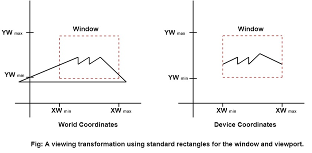
Viewing transformation or window to viewport transformation or windowing transformation: The mapping of a part of a world-coordinate scene to device coordinates is referred to as a viewing transformation etc.
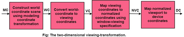
Viewing transformation in several steps:
First, we construct the scene in world coordinate using the output primitives and attributes.
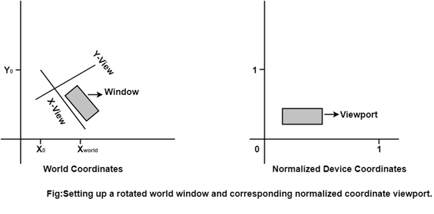
To obtain a particular orientation, we can set up a 2-D viewing coordinate system in the window coordinate plane and define a window in viewing coordinates system.
Once the viewing frame is established, are then transform description in world coordinates to viewing coordinates.
Then, we define viewport in normalized coordinates (range from 0 to 1) and map the viewing coordinates description of the scene to normalized coordinates.
At the final step, all parts of the picture that (i.e., outside the viewport are dipped, and the contents are transferred to device coordinates).
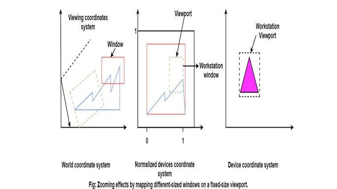
By changing the position of the viewport:We can view objects at different locations on the display area of an output device as shown in fig:
By varying the size of viewports: We can change the size and proportions of displayed objects. We can achieve zooming effects by successively mapping different-sized windows on a fixed-size viewport.
As the windows are made smaller, we zoom in on some part of a scene to view details that are not shown with larger windows.