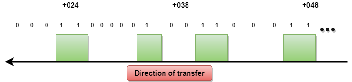
Digital Transmission
Data can be represented either in analog or digital form. The computers used the digital form to store the information. Therefore, the data needs to be converted in digital form so that it can be used by a computer.
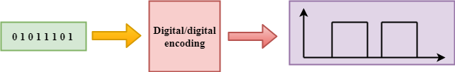
DIGITAL-TO-DIGITAL CONVERSION
Digital-to-digital encoding is the representation of digital information by a digital signal. When binary 1s and 0s generated by the computer are translated into a sequence of voltage pulses that can be propagated over a wire, this process is known as digital-to-digital encoding.
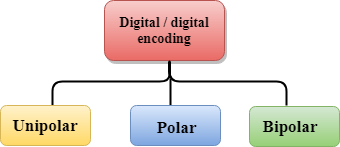
Digital-to-digital encoding is divided into three categories:
- Unipolar Encoding
- Polar Encoding
- Bipolar Encoding
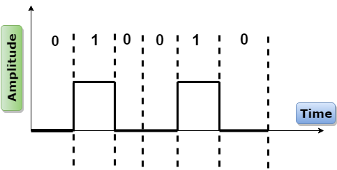
Unipolar
- Digital transmission system sends the voltage pulses over the medium link such as wire or cable.
- In most types of encoding, one voltage level represents 0, and another voltage level represents 1.
- The polarity of each pulse determines whether it is positive or negative.
- This type of encoding is known as Unipolar encoding as it uses only one polarity.
- In Unipolar encoding, the polarity is assigned to the 1 binary state.
- In this, 1s are represented as a positive value and 0s are represented as a zero value.
- In Unipolar Encoding, ‘1’ is considered as a high voltage and ‘0’ is considered as a zero voltage.
- Unipolar encoding is simpler and inexpensive to implement.
Unipolar encoding has two problems that make this scheme less desirable:
- DC Component
- Synchronization
Polar
- Polar encoding is an encoding scheme that uses two voltage levels: one is positive, and another is negative.
- By using two voltage levels, an average voltage level is reduced, and the DC component problem of unipolar encoding scheme is alleviated.
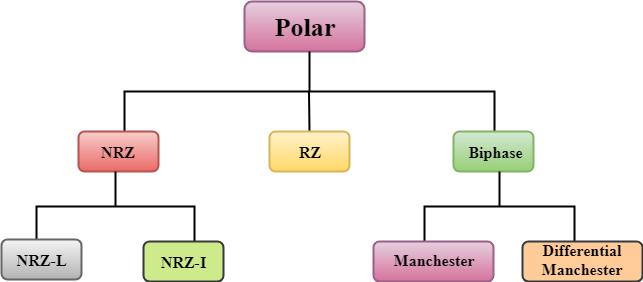
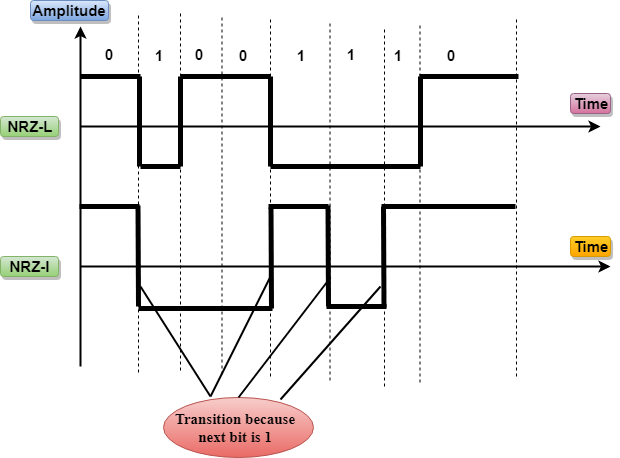
NRZ
- NRZ stands for Non-return zero.
- In NRZ encoding, the level of the signal can be represented either positive or negative.
The two most common methods used in NRZ are:
NRZ-L: In NRZ-L encoding, the level of the signal depends on the type of the bit that it represents. If a bit is 0 or 1, then their voltages will be positive and negative respectively. Therefore, we can say that the level of the signal is dependent on the state of the bit.
NRZ-I: NRZ-I is an inversion of the voltage level that represents 1 bit. In the NRZ-I encoding scheme, a transition occurs between the positive and negative voltage that represents 1 bit. In this scheme, 0 bit represents no change and 1 bit represents a change in voltage level.
RZ
- RZ stands for Return to zero.
- There must be a signal change for each bit to achieve synchronization. However, to change with every bit, we need to have three values: positive, negative and zero.
- RZ is an encoding scheme that provides three values, positive voltage represents 1, the negative voltage represents 0, and zero voltage represents none.
- In the RZ scheme, halfway through each interval, the signal returns to zero.
- In RZ scheme, 1 bit is represented by positive-to-zero and 0 bit is represented by negative-to-zero.
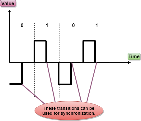
Disadvantage of RZ:
It performs two signal changes to encode one bit that acquires more bandwidth.
Biphase
- Biphase is an encoding scheme in which signal changes at the middle of the bit interval but does not return to zero.
Biphase encoding is implemented in two different ways:
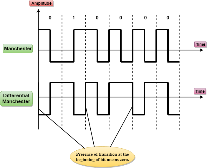
Manchester
- It changes the signal at the middle of the bit interval but does not return to zero for synchronization.
- In Manchester encoding, a negative-to-positive transition represents binary 1, and positive-to-negative transition represents 0.
- Manchester has the same level of synchronization as RZ scheme except that it has two levels of amplitude.
Differential Manchester
- It changes the signal at the middle of the bit interval for synchronization, but the presence or absence of the transition at the beginning of the interval determines the bit. A transition means binary 0 and no transition means binary 1.
- In Manchester Encoding scheme, two signal changes represent 0 and one signal change represent 1.
Bipolar
- Bipolar encoding scheme represents three voltage levels: positive, negative, and zero.
- In Bipolar encoding scheme, zero level represents binary 0, and binary 1 is represented by alternating positive and negative voltages.
- If the first 1 bit is represented by positive amplitude, then the second 1 bit is represented by negative voltage, third 1 bit is represented by the positive amplitude and so on. This alternation can also occur even when the 1bits are not consecutive.
Bipolar can be classified as:
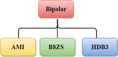
AMI
- AMI stands for alternate mark inversion where mark work comes from telegraphy which means 1. So, it can be redefined as alternate 1 inversion.
- In Bipolar AMI encoding scheme, 0 bit is represented by zero level and 1 bit is represented by alternating positive and negative voltages.
Advantage:
- DC component is zero.
- Sequence of 1s bits are synchronized.
Disadvantage:
- This encoding scheme does not ensure the synchronization of a long string of 0s bits.
B8ZS
- B8ZS stands for Bipolar 8-Zero Substitution.
- This technique is adopted in North America to provide synchronization of a long sequence of 0s bits.
- In most of the cases, the functionality of B8ZS is similar to the bipolar AMI, but the only difference is that it provides the synchronization when a long sequence of 0s bits occur.
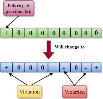
- B8ZS ensures synchronization of a long string of 0s by providing force artificial signal changes called violations, within 0 string pattern.
- When eight 0 occurs, then B8ZS implements some changes in 0s string pattern based on the polarity of the previous 1 bit.
- If the polarity of the previous 1 bit is positive, the eight 0s will be encoded as zero, zero, zero, positive, negative, zero, negative, positive.
- If the polarity of previous 1 bit is negative, then the eight 0s will be encoded as zero, zero, zero, negative, positive, zero, positive, negative.
HDB3
- HDB3 stands for High-Density Bipolar 3.
- HDB3 technique was first adopted in Europe and Japan.
- HDB3 technique is designed to provide the synchronization of a long sequence of 0s bits.
- In the HDB3 technique, the pattern of violation is based on the polarity of the previous bit.
- When four 0s occur, HDB3 looks at the number of 1s bits occurred since the last substitution.
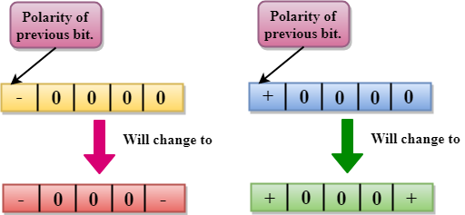
- If the number of 1s bits is odd, then the violation is made on the fourth consecutive of 0. If the polarity of the previous bit is positive, then the violation is positive. If the polarity of the previous bit is negative, then the violation is negative.
If the number of 1s bits since the last substitution is odd.
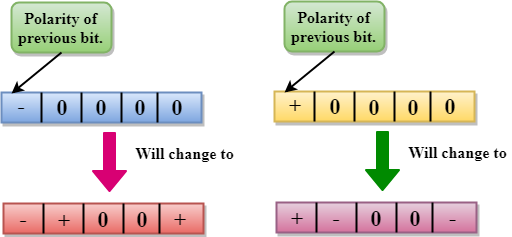
If the number of 1s bits is even, then the violation is made on the place of the first and fourth consecutive 0s. If the polarity of the previous bit is positive, then violations are negative, and if the polarity of the previous bit is negative, then violations are positive.
If the number of 1s bits since the last substitution is even.
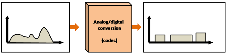
ANALOG-TO-DIGITAL CONVERSION
- When an analog signal is digitalized, this is called an analog-to-digital conversion.
- Suppose human sends a voice in the form of an analog signal, we need to digitalize the analog signal which is less prone to noise. It requires a reduction in the number of values in an analog message so that they can be represented in the digital stream.
- In analog-to-digital conversion, the information contained in a continuous wave form is converted in digital pulses.
Techniques for Analog-To-Digital Conversion
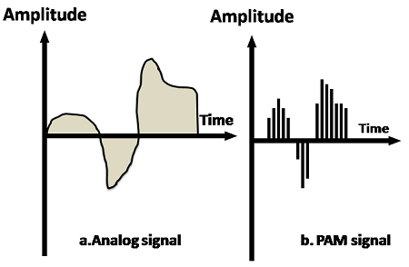
PAM
- PAM stands for pulse amplitude modulation.
- PAM is a technique used in analog-to-digital conversion.
- PAM technique takes an analog signal, samples it, and generates a series of digital pulses based on the result of sampling where sampling means measuring the amplitude of a signal at equal intervals.
- PAM technique is not useful in data communication as it translates the original wave form into pulses, but these pulses are not digital. To make them digital, PAM technique is modified to PCM technique.
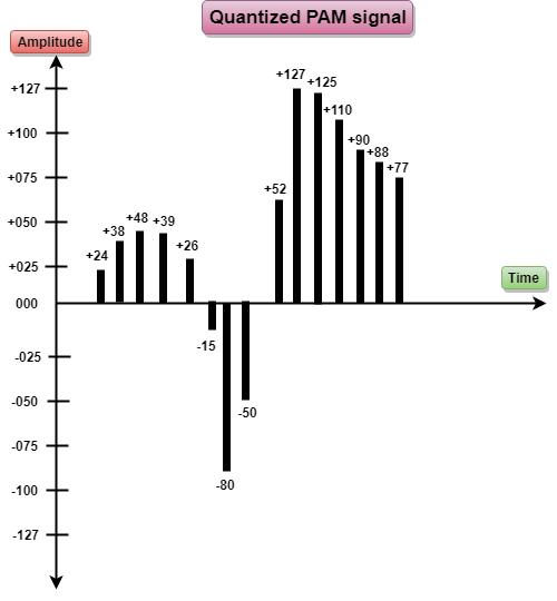
PCM
- PCM stands for Pulse Code Modulation.
- PCM technique is used to modify the pulses created by PAM to form a digital signal. To achieve this, PCM quantizes PAM pulses. Quantization is a process of assigning integral values in a specific range to sampled instances.
- PCM is made of four separate processes: PAM, quantization, binary encoding, and digital-to-digital encoding.
PCM