Control System MCQ
1) A major part of the automatic control theory applies to the:
- Casual systems
- Linear Time invariant systems
- Time variant systems
- Non-linear systems
Answer: (b) Linear Time invariant systems
Explanation: A linear time invariant (LTI) system provides the same output for the same input irrespective of when input is given. LTI systems are also used to predict the system’s long term behavior.
Hence the correct answer is an option (b).
2) Traffic light system is the example of:
- Open-loop system
- Closed-loop system
- Both (a) and (b)
- None of these
Answer: (a) Open-loop system
Explanation: The traffic lamp will glow according to the set timing and sequence and is time-dependent. The sequence and time are controlled by relays that work on the pre-programmed time. It does not depend upon the rush of the road.
Hence the correct answer is an option (a).
3) Laplace transform of a step function shown below is:

- 1
- 1/s^2
- 0
- 1/s
Answer: (d) 1/s
Explanation: The abrupt change in input of a step function takes place at t=0, and the step’s size is1 unit.
Let the size of the step function be A, where A=1.
The Laplace transform of a function is given by:
L[f(t)] = F(s) = ∫0∞f(t) e-st dt
F(s) = ∫0∞Af(t) e-st dt
F(s) = -A/s (e-∞-e-0)
F(s) = A/s
We know, A =1
F(s) = 1/s
Hence the correct answer is an option (d).
4) The negative feedback closed-loop system was subjected to 15V. The system has a forward gain of 2 and a feedback gain of 0.5. Determine the output voltage and the error voltage.
- 15V, 10V
- 6V, 5V
- 15V, 7.5V
- 5V, 10V
Answer: (c) 15V, 7.5V
Explanation:
Given:
G(s) = 2
H(s) = 0.5 and R(s) = 10V
Output voltage: 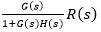
= (2/1+2x 0.5) x 15 = 15V
Error voltage: 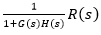
= (1/1+2x 0.5) x 15 = 7.5V
Hence the correct answer is option (c).
5) The Static system can be defined as:
- Output of a system depends on the present as well as past input.
- Output of a system depends only on the received inputs.
- Output of the system depends on future inputs.
- Output of the system depends only on the present input.
Answer: (d) Output of the system depends only on the present input
Explanation: Static systems do not have any feedback system. Hence, the output depends only on the present input.
Hence, the correct answer is an option (d).
6) Find the function f(t) for the following function F(s):
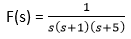
- 0.25e-t+0.05e-5t
- -0.2-0.25e-t+0.05e-5t
- -0.2+0.25e-t+0.05e-5t
- 0.25e-5t+0.05e-t
Answer: (b) -0.2-0.25e-t+0.05e-5t
Explanation: The given function can be written as:
= A/s + B/ (s+1) + C/(s+5)
1 = A(s+1)(s+5) +Bs(s+5) +Cs(s+1)
To calculate the value of A, put s= 0, we get:
1 = A(1)(5)
A = 1/5 = 0.2
Now, to calculate the value of B, put s=-1, we get:
1 = B (-1)(4)
B = -1/4 = -0.25
Similarly, put s=-5, we get:
1 = C (-5) (-4)
C = 1/20 = 0.05
Substituting the value of A, B, and C in F(s), we get:
F(s) = A/s + B/ (s+1) + C/(s+5)
F(s) = 0.2/s – 0.25/ (s+1) + 0.05/(s+5)
We know, Laplace transform of 1/(s + a) = e-atand 1/s = 1.
f(t) = -0.2-0.25e-t+0.05e-5t
Hence the correct answer is option (b).
7) The force equation of the given system is:
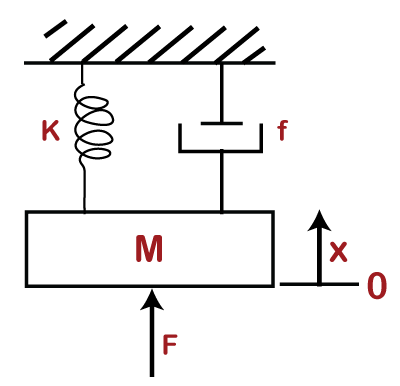
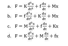
Answer: 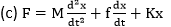
Explanation:
Given: x is the displacement in the above diagram. The Laplace transform of x is X(s). The differential equations governing the system are the balanced force equation at these nodes.
Here,
F is the opposite force due to mass.
F = 
f is the opposite force due to friction
F = 
k is the ideal elastic spring element that has negligible mass and friction. The force generated by the spring is directly proportional to the displacement of the body.
F = Kx
So, the force equation can be represented as:
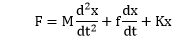
Hence, the correct answer is an option (c).
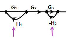
8) Determine the transfer function of the given system:
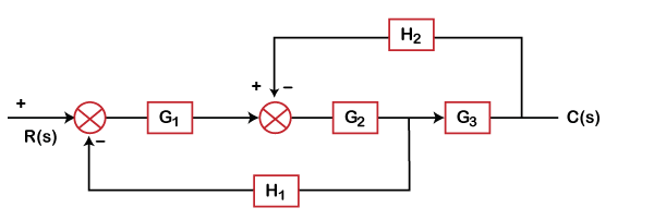
- G1G2G3/ (1 + H2G2G3 + G2G1H1)
- G1 G2G3/ (1 + G1G2G3H2H1)
- G1G2G3 / (1 + G1G2G3H1 + G1G2G3H2)
- G1G2G3 / (1 + G1G2G3H1)
Answer: (a)
Explanation: We will first shift the H1 block after G3
The shifting of a take-off point will make the block as: H1/ G3
Block G2 and G3 are in cascade. The equivalent block will be the product of these two (G2G3).
The gain for that block will be:
G2G3/ (1 + H2G2G3)
As shown, G1 is in cascade, the transfer function of the above system will be:
C(s)/R(s) = [G1G2G3/ (1 + H2G2G3)]/ [1 + G1G2G3/ (1 + H2G2G3) x H1/G3
C(s)/R(s) = G1G2G3/ (1 + H2G2G3 + G2G1H1)
Hence, the correct answer is an option (a).
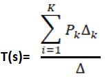
9) Loop gain is equal to:
- Product of all branch gains in a loop
- Product of all branch gains while traversing the forward path
- Summation of all branch gains in a loop
- Sum of all branch gains while traversing the forward path
Answer: (b) Product of all branch gains while traversing the forward path
Explanation: According to Mason’s Gain formula, the transfer function can be calculated as:
T(s) = C(s)/R(s)

Where,
Pk is the forward path gain
∆istheloopgain, which is calculated as:
∆=1-∑(Allloopgain) + ∑(Gainproductoftwonon-touchingloops)-∑(Gainproductofthreenon-touchingloops)
∆k iscalculatedbyeliminatingallloopstouchingPk
Here, the loop gain is defined as the product of the branch gain that is traversing a forward path.
Hence, the correct answer is an option (b).
The Mason’s gain formula is used to find the overall transfer function of a signal graph.
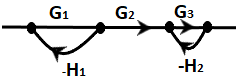
10) Find the overall transfer function of the given signal flow graph.
- G1G2G3/ (1 + G1H1 + G3H2 + G3G1H1H2)
- G1G3/ (1 + G1H1 + G3H2 + G3G1)
- (G1G2G3 + G1H1)/ (1 + G1H1 + G3H2 + G3G1H1H2)
- (G1G2G3 + G1H1 + G3H2) / (1 + G1H1 + G3H2 + G3G1H1H2)
Answer: (a) G1G2G3/ (1 + G1H1 + G3H2 + G3G1H1H2)
Explanation: Here, we will calculate the transfer function using mason’s gain formula:
Where,
Pk is the forward path gain
∆istheloopgain, which is calculated as:
∆=1-∑(Allloopgain) + ∑(Gainproductoftwonon-touchingloops)-∑(Gainproductofthreenon-touchingloops)
∆k iscalculatedbyeliminatingallloopstouchingPk
Now,
Step 1: From the figure, let’s identify the forward path,
P1 = G1G2G3
There is only one forward path in the above figure.
Step 2: Now, let’s find the loop gain. There are two loops:
L1 = -G1H1
L2 = -G3H2
Step 3: Two non-touching loops. There is only one combination of two non-touching loops, as shown below:
L1 L2 = G3G1H1H2
Step 4: Since there are no three non-touching loops, we will directly find the system’s determinant.
∆= 1 – (L1+ L2) + (L1L2)
= 1 + G1H1 + G3H2 + G3G1H1H2
Step 5: Here, we will find ∆1 because there is only one forward path.
For ∆1, we will eliminate L1 and L2 because both loop gains are touching the forward path.
L1 = L2 = 0
∆1=1-0=1
Now, the transfer function is obtained as: C/R = G1G2G3/ (1 + G1H1 + G3H2 + G3G1H1H2)
Hence the correct answer is an option (a).
11) The block diagram representation of a closed-loop system. Write the time response equation for the given system with a unit step input, assuming zero initial conditions.
- 1-e-t⁄5
- 1-et⁄10
- 1-e-t⁄10
- 1+e-t⁄10
Answer: (c) 1-e-t⁄10
Explanation:
The transfer function of a loop is G/ (1+GH)
We will first simplify the above block diagram into the simple system. Let’s calculate the transfer function of the first loop.
TF = [1/ (40s+2)] / [1 + 2/ (40s+2)] = 1/ (40s +4)
Now, two blocks are left in cascade. The equivalent block is the product of these two blocks, as given below:
C(s)/R(s) = 4. (1/ (40s +4)) = 1/ (10s + 1)
The Laplace transform of the step input is 1/s. It means R(s) = 1/s.
C(s) = [1/ (10s + 1)]. R(s)
C(s) = [1/ s (10s + 1)
Taking the inverse Laplace of the above equation, we get:
1-e-t⁄10
12) If the characteristic equation of the closed loop system is s^2 + 2s + 2 = 0, then the system is:
- Over damped
- Critically damped
- Undamped
- Underdamped
Answer: (d) Underdamped
Explanation: The given equation is: s^2 + 2s + 2 = 0
It is a second-order differential equation. The Laplace transform of a standard form of a second-order differential equation is:
Thus, the system is underdamped.
Hence, the correct answer is an option (d).
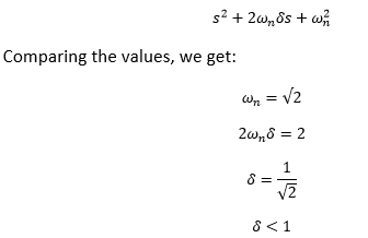
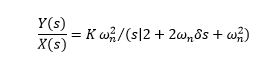
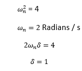
13) The transfer function of a system is given as 81/ (s^2 + 16s + 81). Find the undamped natural frequency, damping ratio, and peak time for a unit step input.
- 9, 0.889, 0.762
- 9, 0.559, 0.762
- 9, 0.889, 0.187
- 9, 0.667, 0.187
Answer: (a) 9, 0.889, 0.762
Explanation: The standard transfer function can be written as:
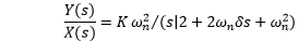
The given equation is: 81/ (s^2 + 16s + 81)
Comparing the values, we get:
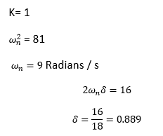
Thus, the undamped natural frequency is 9, and the damping ratio is 0.889.
The Peak time can be calculated as:
Hence, the correct answer is an option (a).
14) The closed loop transfer function for a second order system is: T(s) = 4/ (s^2 + 4s + 4). Calculate the settling time for a 2 percent and 5 percent band.
- 5, 2.0
- 0, 10.0
- 0, 1.5
- 0, 2.0
Answer: (c) 2.0, 1.5
Explanation: The standard transfer function can be written as:
The given equation is: 4/ (s^2 + 4s + 4)
Comparing the values, we get:
K= 1
The settling time for a 2 percent band is calculated as:
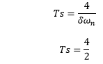
Settling time = 2 seconds
The settling time for a 5 percent band is calculated as:
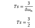
Settling time = 1.5 seconds
Hence, the correct answer is an option (c).
15) Consider a system with transfer function G(s) = (s + 4)/ (ks^2 + s + 4). The value of damping ratio will be 0.5 when the value of k is:
- ½
- ¼
- 8
- 4
Answer: (b) ¼
Explanation: The given transfer function is:
G(s) = (s + 4)/ (ks^2 + s + 4)
The characteristic equation ks^2 + s + 4 = 0
Dividing the equation by k, we get:
S^2 +s/k + 4/k = 0
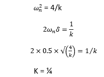
Hence, the correct answer is an option (b).
16) The step error coefficient of a system G(s) = 1/ (s+2)(s+3) with unity feedback is:
- 0
- Infinite
- 1
- 1/6
Answer: (d) 1/6
Explanation: The step error can be calculated as:
ess = sR(s)/ (1 + G(s))
R(s) = 1/s (in case of unity feedback)
G(s) = 1/ (s+2)(s+3)
ess = (s x 1/s )/ (1 + (1/ (s+2)(s+3)))
ess = 1/(1 + kp)
Where, kp is the step error coefficient
Kp can be calculated as:
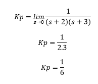
Hence, the correct answer is an option (d).
17) The transfer function of a control system is given by G(s) = 25/ (s^2 + 6s + 25). The first maximum value of the response occurs at t, which is given by:
- π⁄2
- π⁄8
- π⁄4
- π
Answer: (c) π⁄4
Explanation: The given transfer function is: G(s) = 25/ (s^2 + 6s + 25)
Comparing the value of the given transfer function with the standard equation
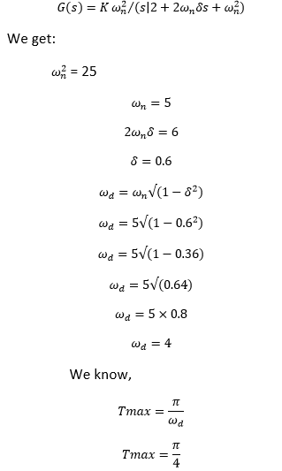
Hence, the correct answer is option (c).
18) The impulse response of an RL circuit is:
- Parabolic function
- Step function
- Rising exponential function
- Decaying exponential function
Answer: (d) Decaying exponential function
Explanation: The RL circuit comprises of the resistor and inductor connected in series.
The equation can be written as:
1 = RI(s) + sLI(s)
1 = I(s) [R + sL]
I(s) = 1 / (R +sL)
Taking the inverse Laplace, we get:

The equation clearly depicts that the impulse response is a decaying exponential function.
Hence, the correct answer is option (d).
19) Calculate the poles and zeroes for the given transfer function G(s) = 5 (s + 2)/ (s^2 + 3s + 2)
- -2, (-1, -2)
- 2, (-1, 2)
- 2, (1, 2)
- -2, (1, -2)
Answer: (a) -2, (-1, -2)
Explanation: The zeroes can be calculated by equating the numerator to zero:
5 (s + 2) = 0
5s + 10 = 0
5s = -10
s = -2
The poles can be calculated by equating the denominator to zero:
s^2 + 3s + 2 = 0
s^2 + 2s + s + 2 = 0
s (s + 2) + 1 (s + 2) = 0
(s + 1) (s + 2) = 0
s = -1, -2
Hence, the correct answer is an option (a).
20) The number of roots in the left half of the s-plane of the given equation s^3 + 3s^2 + 4s + 1 = 0 is:
- One
- Three
- Two
- Zero
Answer: (b) Three
Explanation: The given characteristic equation is: s^3 + 3s^2 + 4s + 1 = 0.
To find the number of roots, we need to create a Routh table, as shown below:
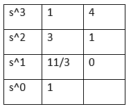
There are no roots and no significant changes in the RHS plane, as shown in the above table. Hence, all three roots lie in the LHS plane.
Hence, the correct answer is an option (b).
21) A system with the polynomial s^4 + 5s^3 + 3s^2 + 6s + 5 = 0 is:
- Unstable
- Marginally stable
- In equilibrium
- Stable
Answer: (a) Unstable
Explanation: The given characteristic equation is: s^4 + 5s^3 + 3s^2 + 6s + 5 = 0. We first need to find the roots by creating the Routh’s array table.
Routh’s array table is shown below:
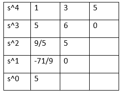
In the first column of the above table, we have two sign changes. It means that two roots are in the RHS plane. Hence, the system is unstable.
Hence the correct answer is an option (a).
22) If s^3 + Ks^2 + 5s + 10 = 0, the root of the feedback system’s characteristic equation is said to be critically stable. Then, the value of K will be:
- 1
- 2
- 3
- 4
Answer: (b) 2
Explanation: For the above equation, we need to find the roots by creating the Routh’s array table. The given equation is: s^3 + Ks^2 + 5s + 10
The table is given below:
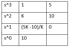
For the system to be critically stable, we will put (5K -10)/K = 0
5K – 10 = 0
5K = 10
K = 2
The value of K for which the system is said to be critically stable is 2.
Hence, the correct answer is an option (b).
23) If s^3 + 3s^2 + 4s + A = 0, the roots of the characteristic equation lie in the left half of the s-plane. The value of the A is said to be:
- 0 < A < 12
- 5< A < 12
- A > 12
- A < 12
Answer: (a) 0 < A < 12
Explanation: For the above equation, we need to find the roots by creating the Routh’s array table. The given equation is: s^3 + 3s^2 + 4s + A = 0
The table is given below:
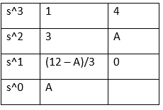
There is no change in sign in the first column of the Routh table. It means that all roots lies in the left half of the s-plane.
Putting A and (12 – A)/3 > 0, we get:
A > 0 (or 0 < A)
(12 – A)/3 > 0
12 – A > 0
12 > A (or A < 12)
From the above equations, we get two values of A, i.e., A > 0 and A < 12. It means that A lies between 0 and 12, as shown below:
0 < A < 12
Hence, the correct answer is an option (a).
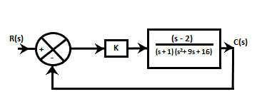
24) For the given closed-loop system, the ranges of the values of K for stability is:
- K > -19.5
- k > 8
- -19.5 < k < 8
- K > 0
Answer: (c) -19.5 < k < 8
Explanation: The two blocks in the above diagram are in cascade. So, the equivalent block will be the product of these two blocks.
G(s) = k (s – 2) /(s +1) (s^2 + 9s + 16)
Now, H(s) = 1, as shown in the above block diagram. The characteristic equation will be: 1 + G(s) H(s)
C(s) = 1 + [k (s – 2) / (s + 1) (s^2 + 9s + 16)] = 0
= s^3 + 10s^2 + 25s + 16 + ks – 2k
= s^3 + 10s^2 + s (25 + k) + 16 – 2k
For the above equation, we need to find the roots by creating the Routh’s array table.
The table is given below:
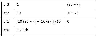
For stability,
16 – 2k > 0
16 > 2k
8 > k or k < 8
10 (25 + k) – (16 -2k) /10 > 0
250 + 10k -16 + 2k > 0
12k + 234 > 0
12k > -234
k > -19.5
From the two values of k, we can say that it lies between -19.5 < k < 8
Hence, the correct answer is an option (c).
25) Find the number of asymptotes for the given open-loop transfer function of a unity feedback system:
G(s) = ((s + 2) (s+3) (s + 4)) / ((s + 5) (s+6) (s + 1))
- 1
- 0
- 2
- 3
Answer: (b) 0
Explanation: The number of asymptotes in a given system is equal to the number of branches approaching infinity. So, the formula to calculate the number of asymptotes is P -Z. Here, P and Z represent the poles and zeroes.
We know that poles and zeroes are calculated by equating the denominator and numerator to zero. So, for the given open-loop transfer function, we get:
P = 3
Z = 3
So, the number of zeroes at infinity = 3 – 3 = 0
Hence, the correct answer is an option (b).
26) An open loop transfer function is given by G(s) = K (s + 1) / (s + 4)(s^2 + 3s + 2). It has:
- One zero at infinity
- Three zeroes at infinity
- Two zeroes at infinity
- None of the above
Answer: (c) Two zeroes at infinity
Explanation: The formula to calculate a number of zeroes at infinity is P – Z. Here, P and Z are the number of poles and zeroes in a given transfer function.
We know that poles are calculated by equating the denominator to zero, and zeroes are calculated by equating the numerator to zero. So, for the above given transfer function, we get:
P = 3
Z = 1
So, the number of zeroes at infinity = 3 – 1 = 2
Hence, the correct answer is an option (c).
27) The centroid in the root locus is a point where
- The branches of the root locus intersect with the imaginary axis.
- The branches of the root locus tend to infinity.
- The asymptotes cross the real axis.
- The branches of the root locus terminate on the real axis.
Answer: (c) The asymptotes cross the real axis.
Explanation: Centroid is defined as a common point where all the asymptotes intersect on the real axis. The value of centroid is always real. But, it can be located either on the positive or negative real axis.
28) Calculate the centroid for the given system:
G(s) = K / [(s + 1) (s + 4 + 4j) (s + 4 – 4j)]
- – 1.47
- -2
- -2.66
- -3
Answer: (d) -3
Explanation:
We will first calculate the number of branches approaching infinity and then the asymptotes. With the help of asymptotes, we will calculate the value of centroid.
The given transfer function of the system is G(s) = K / [(s + 1) (s + 4 + 4j) (s + 4 – 4j)].
The number of asymptotes is equal to the number of branches approaching infinity. There are no zeroes but three poles.
So, P – Z = 3
Let’s calculate the value of the poles by equating the denominator equal to zero. We get:
Poles located at: -1,
The angle of asymptotes is calculated by:
Θ = (2q + 1) 180 / (P – Z)
Here, q = 0, 1, 2…
The number of asymptotes is equal to the number of branches approaching infinity.
So, we will calculate the asymptotes at value 0, 1, and 2.
For q = 0,
Θ=180⁄3=60degrees
For q = 1,
Θ=(2+1) 180⁄3=180degrees
For q = 2,
Θ=(4+1) 180⁄3=300degrees
Centroid is defined as a common point where all the asymptotes intersect on the real axis.
σ= / (P – Z)
σ= (- 1 – 4 – 4 – 0) / 3
σ=(-9)⁄3
σ=-3
Hence, the correct answer is an option (d).
29) The characteristic equation of the feedback control system is given as: s^3 + 4s^2 + (K + 5)s + K = 0
Here, K is a scalable variable parameter. In the root loci diagram of the system, the asymptotes of the root locus for large values of K meet at a point in the s-plane whose coordinate is:
- (-1.5, 0)
- (-2, 0)
- (-1, 0)
- (2, 0)
Answer: (b) (-2, 0)
Explanation:
The given equation for the feedback control system is s^3 + 5s^2 + (K + 6)s + K = 0.
The above equation can also be written as:
s^3 + 5s^2 + Ks + 6s + K = 0
s^3 + 5s^2 + 6s + K(s + 1) = 0
s (s^2 + 5s + 6) + K(s + 1) = 0
1 + K(s + 1) / [s (s^2 + 5s + 6)] = 0
1 + K(s + 1) / s (s^2 + 2s + 3s + 6) = 0
1 + K(s + 1) / s (s + 2)(s + 3) = 0
Now, we will calculate the value of centroid, which is equal to:
σ= / (P – Z)
Here, the number of poles and zeroes are 3 and 1.
σ= [(0 – 2 – 3) + 1] / (3 – 1)
σ=(-4)⁄2
σ=-2
Hence, the correct answer is option (b).
30) In a bode-plot of a unity feedback control system, the value of phase of G(jw) at the gain cross over frequency is -115 degrees. The phase margin of the system is:
- 115 degrees
- -57.5 degrees
- -65 degrees
- 65 degrees
Answer: (d) 65 degrees
Explanation: The phase margin can be calculated as 180 +
Where,
∅ is the phase of G(jw) at the gain cross over frequency.
So, phase margin = 180 + (-115)
= 180 – 115
= 65 degrees
Hence, the correct answer is an option (d).
31) The gain margin of a second-order system is:
- Zero
- Infinite
- One
- Two
Answer: (b) Infinite
Explanation: The gain margin indicates the additional gain provided to the system without affecting its stability.
The total phase shift of a second-order system is approximately equal to 180 degrees, which leads to the infinite frequency. Thus, the gain margin is also infinite.
Hence, the correct answer is an option (b).
32) Determine the phase cross-over frequency of the given open-loop transfer function:
G(s) = 1 / s(s + 1) (2s + 1)
- 606 Radians / second
- – 1. 707 Radians / second
- 707 Radians / second
- – 0. 707 Radians / second
Answer: (c) 0. 707 Radians / second
Explanation: The given open-loop transfer function is: G(s) = 1 / s(s + 1) (2s + 1)
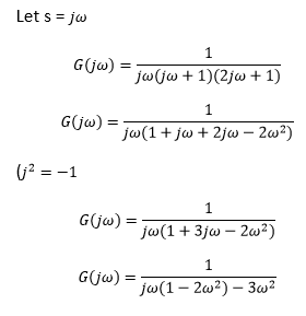
The imaginary part of the system at phase cross over frequency is zero. Hence, we will equate the imaginary part to zero, as shown below:
It means that the phase cross-over frequency to the system is 0.707 Radians/s.
Hence, the correct answer is an option (c).
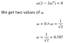
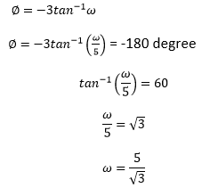
33) Determine the gain margin of the given open-loop feedback control system: G(s)H(s) = 1 / [(s + 1) ^3]
- 2
- 4
- 8
- 32
Answer: (c) 8
Explanation: The given open-loop feedback control system is: G(s)H(s) = 1 / [(s + 1) ^3]
The phase angle for the cross-over frequency can be calculated by:
-3 tan-1 ω=-180°
We get the value of ω=√3
Now, the gain margin is the magnitude of the transfer function, as shown below:
= 1 / |G(s)H(s)| = |(j√3+13|
= 8
Hence, the correct answer is an option (c).
34) The phase margin of the given system G(s) = 1 / [(s + 1) ^3] is:
- Π
- -Π
- 0
- Π/2
Answer: (a) Π
Explanation: The phase margin can be calculated as: 180 + ∅
Where,
∅ is the phase of G(jω) at the gain cross over frequency.
We will first find the magnitude of the given system, as shown below:
Hence, the correct answer is an option (a).
35) The corner frequency in the Bode plot is:
- The frequency at which bode plot slope is 0 dB /decade.
- The frequency at which bode plot slope is -10 dB /decade.
- The frequency at which the two asymptotes intersect.
- The frequency at which the two asymptotes meet.
Answer: (d) The frequency at which the two asymptotes meet.
Explanation: The frequency at which the two asymptotes in the Bode plot meet is termed as corner frequency.
Hence, the correct answer is an option (d).
36) Which of the following statements are correct?
1. Bode plot is in the frequency domain.
2. Root locus is in the time domain.
3. Nyquist criteria are in the frequency domain.
4. Routh Hurwitz’s criteria are in the time domain.
- 1 and 2
- 1 and 3
- 1, 3, and 4
- 2 and 3
Answer: (b) 1 and 3
Explanation: The Bode plot is defined as the frequency response plot of the sinusoidal transfer function of a system. The two graphs of the Bode plot are the plot of magnitude and phase angle. Thus, it is in the frequency domain.
The Nyquist plot is considered as the extension of the polar plot. The variation of frequency from infinity to -infinity results in the plot, known as the Nyquist plot. Hence, the Nyquist criterion is in the frequency domain.
Hence, the correct answer is an option (b).
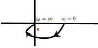
37) Determine the type and order of the given Nyquist plot:
- 1, 2
- 0, 1
- 2, 1
- 0, 2
Answer: (d) 0, 2
Explanation: The given plot is of the type 1/ (ST1 + 1)(ST2 + 1)
The above transfer function has order 2 and type 0.
Hence, the correct answer is an option (d).
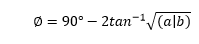
38) Calculate the damping ratio of the system whose phase margin is 45 degrees.
- 1
- 42
- 5
- 0
Answer: (b) 0.42
Explanation: The formula to calculate the damping ratio using the phase margin is:
Damping Ratio = tan∅√cos ∅⁄2
= ((tan45√cos45))⁄2
= 0. 42
Hence, the correct answer is an option (b).
39) The GM of a unity feedback system with the transfer function 1/ (s + 5)^3 is:
- 10 dB
- 30 dB
- 60 dB
- 40 dB
Answer: (c) 60 dB
Explanation: The Phase margin can be calculated as:
The gain margin (GM) = 20 log (1 / |G(s)H(s)|)
At, s = jω
We get: (GM) = 60dB
Hence, the correct answer is an option (c).
40) The most powerful controller is:
- PD controller
- PI Controller
- PID Controller
- None of the above
Answer: (c) PID Controller
Explanation: The PID is the combination of proportional, integral, and derivate control modes. Such a combination makes it the most powerful controller.
Hence, the correct answer is an option (c).
41) What will be the controller output for PD controller at t = 2s, if the error begins to change from 0 at the rate of 1.2% /s? The given parameters are Po = 50%, Kp = 4, and KD = 0.4.
- 61.52%
- 61.92%
- 51.52%
- 51.92%
Answer: (a) 61. 52%
Explanation: The error the rate of 1.2% per second c neb calculated as:
e = 1.2% x 2 = 1.2/100 x 2 = 2.4%
Now, let’s calculate the Pout (controller output) = 4 (2.4%+ KD x 1.2%) + Po
= 4 (2.4 / 100 + 0.4 x 1.2 /100) + 50/100
= 4 x 2.88/100 + 50/100
= 11.52/100 + 50/100
= 61.52/100
= 61.52%
Hence, the correct answer is an option (a).
42) The controller required to handle fast process load changes is:
- PD controller
- PI Controller
- PID Controller
- None of the above
Answer: (a) PD controller
Explanation: The Proportional Derivative controller is preferred to handle fast process load changes.
Hence, the correct answer is an option (a).
43) Consider the following statements:
1. Lead compensator increases the bandwidth of the system.
2. Lag compensator suppresses steady-state performance.
3. Lead compensator improves the dynamic response and provides faster response.
4. Lag compensator acts as a low-pass filter.
Of these above statements, which of the following are true?
- 1 and 2
- 1, 2, and 3
- 1, 2, and 4
- 3 and 4
Answer: (c)
Explanation: Lag compensator does not suppress steady state performance. Instead, it improves steady state performance.
Hence, the correct answer is an option (c).
44) The transfer function of a compensating network is in the form of (1 +aTs) / (1 + Ts). Find the value of ‘a’ if the given network is the phase-lag network.
- Between 0 and 1.
- 0
- 1
- Greater than 1
Answer: (a) Between 0 and 1
Explanation: The given transfer function is:
(1 +aTs) / (1 + Ts)
We will first calculate the poles and zeroes of the given transfer function.
Here,
Zero = -1/aT
Pole = -1/T
The pole in the given system is nearer to the jω axis (origin). The 0 will be far from the axis, such that the value of a < 1. It means that the value lies between 0 and 1.
Hence, the correct answer is an option (a).
45) Consider the following statements:
Phase lead:
1) Increases the bandwidth of the system
2) Improves the damping
3) Reduces steady-state error
4) Increases gain at high frequency
Which of the following statements are true?
- 1 and 2
- 2 and 4
- 1, 2, and 3
- 1 and 4
Answer: (d)
Explanation: Phase lead is responsible for improving the damping and reducing the system’s steady-state error.
Hence, the correct answer is an option (d).
46) Find the phase shift provided by the lead compensator for a given transfer function G(s) = (1 + 6s)/ (1 + 2s)
- 15 degrees
- 30 degrees
- 45 degrees
- 60 degrees
Answer: (b) 30 degrees
Explanation: The phase shift provided by the lead compensator can be calculated using the formula:
The standard transfer function of a lead compensator is represented as:
(s +1/aT) / (s + 1/bT)
Comparing the value of the given transfer function to the standard transfer function, we get:
a = 1/6
b = 1/2
Putting the values of a and b in the phase shift formula:
Hence, the correct answer is an option (b).
47) The following set of differential equations describes a linear second-order single input continuous-time system.
X1′(t) = -2X1(t) + 4X2(t)
X2′(t) = 2X1(t) – X2(t) + u(t)
Here, X1(t) and X2(t) are the state variables, and u(t) is the control variable. Check for the system, if it is:
- Uncontrollable and unstable
- Controllable but unstable
- Controllable and stable
- Uncontrollable and stable
Answer: (b) Controllable but unstable
Explanation:
We know,
Here,
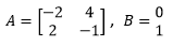
The product of matrix A and B is,
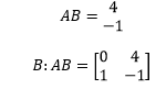
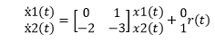
Thus, the rank of the system is 2.
The determinant of the system is non-zero. Hence, the system is controllable.
Now, we will check for stability.
SI – A = 0
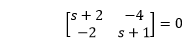
The above matrix can be written in the form of an equation:
s^2 + 3s -6 = 0
Now, we will find the roots using Routh’s array table, as shown below:
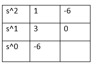
There are two sign changes in the first column. Thus, the system is unstable.
Hence, the correct answer is an option (b).
48) The sum of the Eigenvalues in the given matrix is:
- The sum of all non-zero components in the matrix
- Sum of the elements of any row
- Sum of the elements of any column
- Sum of the principal diagonal elements
Answer: (d) Sum of the principal diagonal elements
Explanation: The sum of Eigenvalue of a given matrix is generally called the trace of that matrix. The trace of a matrix is the sum of the diagonal elements of a matrix.
Hence, the correct answer is an option (d).
49) Consider a LTI system described by the given differential equation:
d^2 a(t)/dt^2 + 3da(t)/dt + 2a(t) = r(t)
Where a(t) is the output. The Eigenvalues of the given characteristic equation are:
- 2, 1
- 2, -1
- -2, 1
- -2, -1
Answer: (d)
Explanation: Let x1(t) = a(t) and x2(t) = ẋ1
Thus, the given characteristic equation can be written as:
ẋ2 +3×2 + 2×1 = r(t)
The matrix representation will be:
Where, A is the matrix:
We know the characteristic equation to calculate Eigenvalue is |SI – A| = 0
The equation thus formed is:
s (s + 3) + 2 = 0
s^2 + 3s + 2 = 0
s^2 + 2s + s + 2 = 0 (factorization to find Eigenvalues)
(s + 2)(s + 1) = 0
S = -2, -1
Thus, the required Eigenvalues are -2 and -1.
Hence, the correct answer is an option (d).
50) The signal flow graph shown in the figure has:
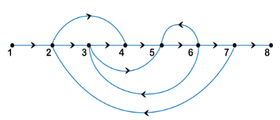
- forward path = 2, loops = 4, and non-touching loops = 0
- forward path = 3, loops = 4, and non-touching loops = 0
- forward path = 3, loops = 3, and non-touching loops = 0
- forward path = 2, loops = 4, and non-touching loops = 2
Answer: (c) forward path = 3, loops = 3, and non-touching loops = 0
Explanation: Forward path is the path from the input to the output node in the given signal flow graph. Here, there are three forward paths.
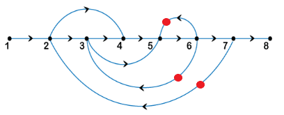
The number of loops in the given signal flow graph is three, as shown in the below image:
The non-touching loops are considered as non-touching when there are no common nodes between them. There are no non-touching loops in the given signal flow graph. It is because all the loops touch each other.
Hence, the correct answer is an option (c).
51) Arrange the following set of statements in order.
The free-body diagram is obtained,
1. By marking all the forces acting on the node
2. Drawing each mass separately.
3. Take Laplace transform of differential equations and rearrange the equations in the s-domain.
4. Find the transfer function as the ratio between output and input variable.
5. Write one differential equation for each of the free body diagram.
- 1, 2, 3, 4, 5
- 2, 1, 5, 3, 4
- 1, 3, 2, 5, 4
- 2, 1, 4, 3, 5
Answer: (b) 2, 1, 5, 3, 4
Explanation: The correct order to find the transfer function of the free body diagram is given below:
The free-body diagram is created by drawing each mass separately and marking all the forces acting on the node. Write one differential equation for each of the free body diagram and take the Laplace transform and convert the differential equations into the algebraic equations. Rearrange the equations in the s-domain to find the output and input ratio by eliminating the unwanted variables. In this way, we can easily calculate the transfer function of the free body diagram.
Hence, the correct answer is an option (b).