300
Full – Adder
This circuit needs three binary inputs and two binary outputs. The truth table for a full-adder is:
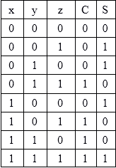
- Two of the input variable ‘x’ and ‘y’, represent the two significant bits to be added.
- The third input variable ‘z’, represents the carry from the previous lower significant position.
- The outputs are designated by the symbol ‘S’ for sum and ‘C’ for carry.
- The eight rows under the input variables designate all possible combinations of 0’s, and 1’s that these variables may have.
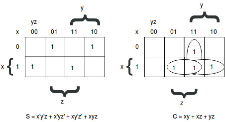
- The input-output logical relationship of the full-adder circuit may be expressed in two Boolean functions, one for each output variable.
- Each output Boolean function can be simplified by using a unique map method.
Maps for a full-adder:
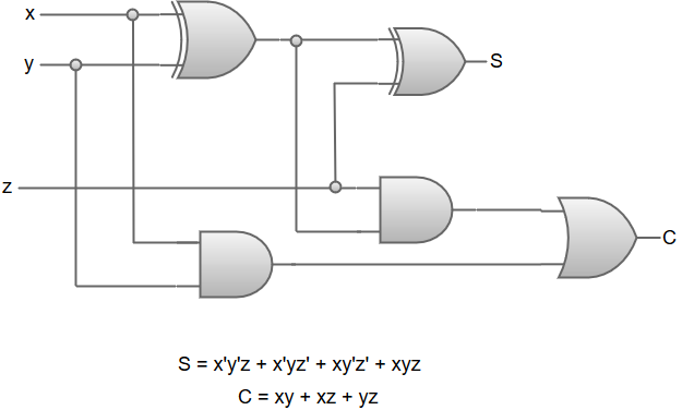
The logic diagram for a full-adder circuit can be represented as:
Next TopicS-R Flip-Flop