Half Adder
The Half-Adder is a basic building block of adding two numbers as two inputs and produce out two outputs. The adder is used to perform OR operation of two single bit binary numbers. The augent and addent bits are two input states, and ‘carry‘ and ‘sum ‘are two output states of the half adder.
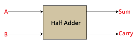
Block diagram
Truth Table
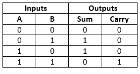
In the above table,
- ‘A’ and’ B’ are the input states, and ‘sum’ and ‘carry’ are the output states.
- The carry output is 0 in case where both the inputs are not 1.
- The least significant bit of the sum is defined by the ‘sum’ bit.
The SOP form of the sum and carry are as follows:
Sum = x’y+xy’
Carry = xy
Construction of Half Adder Circuit:
In the block diagram, we have seen that it contains two inputs and two outputs. The augent and addent bits are the input states, and carry and sum are the output states of the half adder. The half adder is designed with the help of the following two logic gates:
- 2-input AND Gate.
- 2-input Exclusive-OR Gate or Ex-OR Gate
1. 2-input Exclusive-OR Gate or Ex-OR Gate
The Sum bit is generated with the help of the Exclusive-OR or Ex-OR Gate.
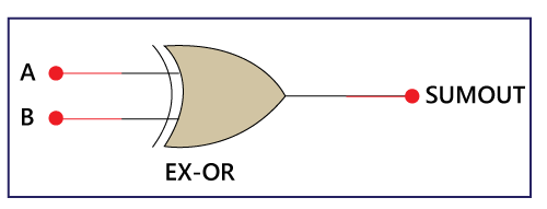
The above is the symbol of the EX-OR gate. In the above diagram, ‘A’ and ‘B’ are the inputs, and the ‘SUMOUT’ is the final outcome after performing the XOR operation of both numbers.
The truth table of the EX-OR gate is as follows:
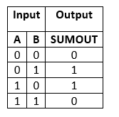
From the above table, it is clear that the XOR gate gives the result 1 when both of the inputs are different. When both of the inputs are the same, the XOR gives the result 0. To learn more about the XOR gate, click here.
2. 2-input AND Gate:
The XOR gate is unable to generate the carry bit. For this purpose, we use another gate called AND Gate. The AND gate gives the correct result of the carry.
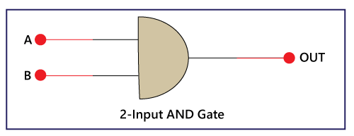
The above is the symbol of the AND gate. In the above diagram, ‘A’ and ‘B’ are the inputs, and ‘OUT’ is the final outcome after performing AND operation of both numbers.
There is the following truth table of AND Gate:
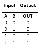
From the above table, it is clear that the AND gate gives the result 1 when both of the inputs are 1. When both of the inputs are different and 0, the AND gates gives the result 0. To learn more about the AND gate, click here.
Half-Adder logical circuit:
So, the Half Adder is designed by combining the ‘XOR’ and ‘AND’ gates and provide the sum and carry.
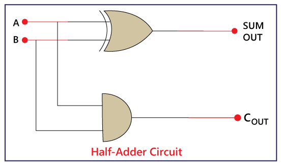
There is the following Boolean expression of Half Adder circuit:
Sum= A XOR B (A+B)
Carry= A AND B (A.B)