External Interrupts in AVR Microcontroller
Microcontrollers can accept inputs from I/O ports, interrupts are used for accepting inputs generated by external events. Interrupt event directs the flow of program execution with a totally independent piece of code, known as “Interrupt Sub-Routine”. There are many sources of interrupts that are available for a microcontroller. Most of them are generated by internal modules and are called as internal interrupts.
For running an interrupt subroutine following requirements are necessary:
- The interrupt source must be activated by setting the corresponding interrupt mask/ Interrupt Enable Bit.
- The enable bit in AVR status register must be set to 1. For this the instruction named ‘sei’ (Set Interrupt Enable).
- The interrupt sub routine must present. If there is no code to b e run, then an empty subroutine must occur at particular memory spaced to that interrupt.
- Finally the event must occur, so the execution of the routine gets triggered.
Writing an Interrupt Subroutine in AVR Studio:
It is tricky to use an interrupt subroutine into a C code of a microcontroller. Therefore the AVR GCC developers use a few symbols to represent the interrupts and macros that minimized the code size in many programs.
The interrupt subroutine for External Interrupt 0 and External Interrupt 1 is given below:
Registers Associated with External Interrupts:
The table showing microcontroller unit control register is given below:
| MCU Control Register- MCUCR | ||||||||
|---|---|---|---|---|---|---|---|---|
| Bit | 7 | 6 | 5 | 4 | 3 | 2 | 1 | 0 |
| Bit Name | SE | SM2 | SM1 | SM0 | ISC11 | ISC10 | ISC01 | ISC00 |
| Initial value | 0 | 0 | 0 | 0 | 0 | 0 | 0 | 0 |
| Read/Write | RW | RW | RW | RW | RW | RW | RW | RW |
The table showing Interrupt Sense Control truth table is:
| ISCx1 | ISCx0 | Interrupt Generated Upon |
|---|---|---|
| 0 | 0 | The lower Level of INTx pin |
| 0 | 1 | Any logical change inside INTx pin |
| 1 | 0 | Falling edge of INTx pin |
| 1 | 1 | Rising edge of INTx pin |
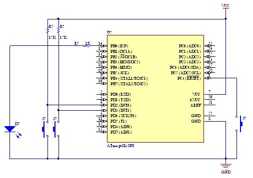
Circuit Diagram:
Source Code: