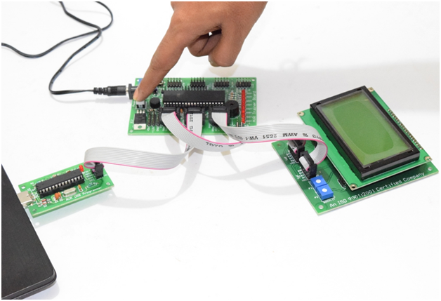
LCD Interfacing with AVR
For interfacing LCD with AVR, an 8 bit data bus is required. In addition we require 2 bit control bus for write mode or 3 bit control bus for write plus read mode. Connect the pin 1 of the LCD module to ground, pin 2 to +ive supply. Connect the potentiometer (2 to 5 k Ohm) across the ground and supply. Connect the middle pin of the potentiometer with a pin-3 of LCD module.
The 8 bit mode interfacing of the LCD display with an AVR microcontroller is shown below:-
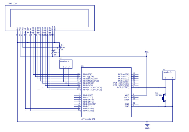
1) Interfacing LCD with ATmega8 Microcontroller:
The electronic circuit diagram for interfacing LCD with ATmega8 microcontroller is:
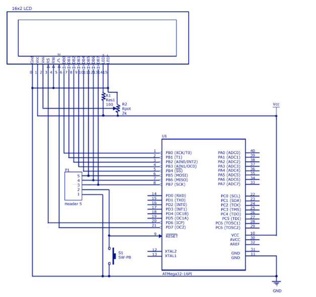
2) Interfacing LCD with ATmega32 Microcontroller:
The electronic circuit diagram for interfacing LCD with ATmega32 microcontroller is:
In LCD two separate routines are used for two separate cycles. One is used for transfer the data or character and another is used for sending the command inside an embedded system.
For preventing the crash of data, we must allow the LCD to complete the execution of each operation. In this we use delay loops available from the AVR studio Library. Each instruction or data takes at least of 40micro second to get executed and the longest wait loop is around 1.65 ms.
The embedded C code for displaying TutorAspire on LCD screen using AVR microcontroller is given below:
LCD Interfacing with AVR Microcontroller connections: