LR Rotation
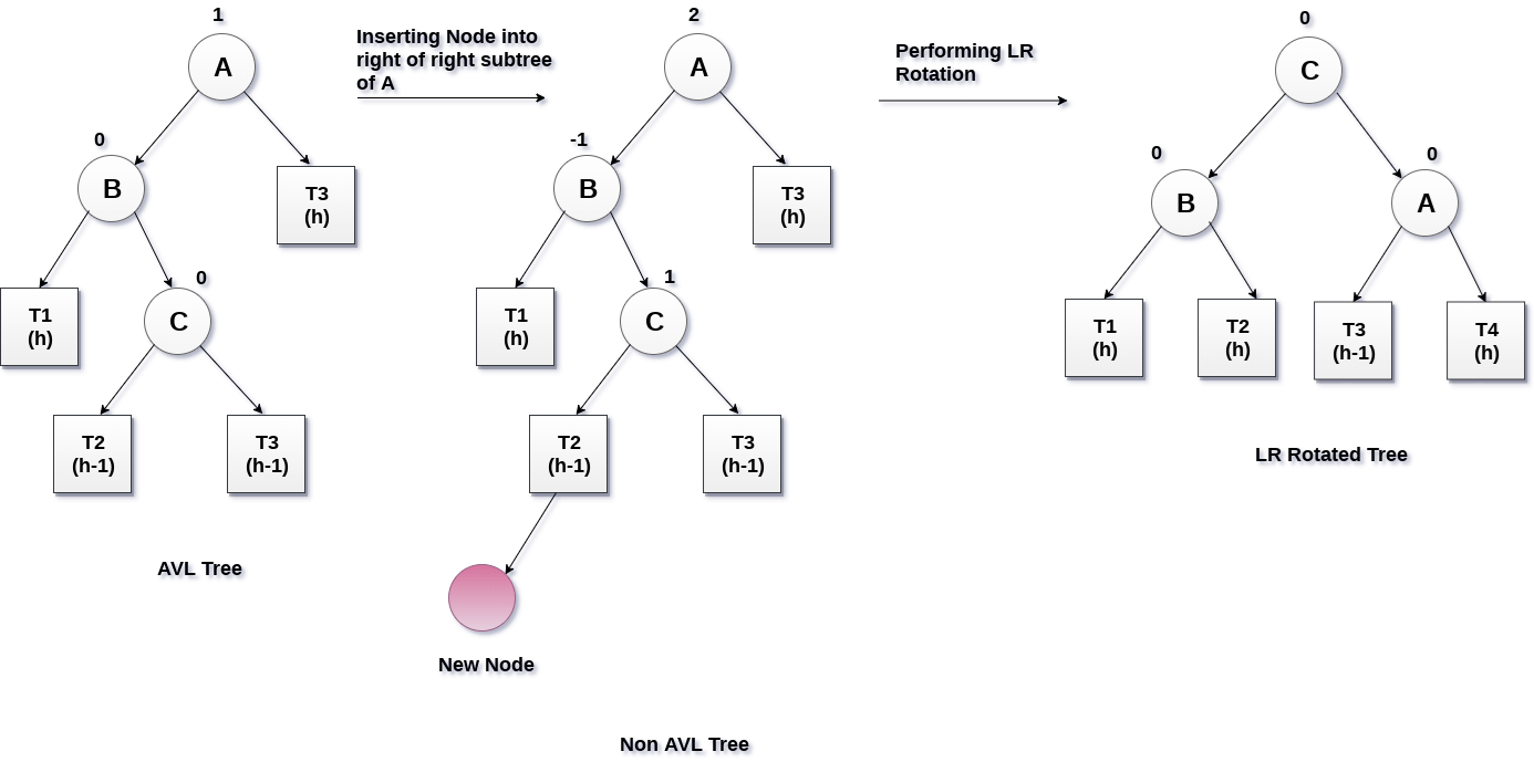
LR rotation is to be performed if the new node is inserted into the right of the left sub-tree of node A.
In LR rotation, node C (as shown in the figure) becomes the root node of the tree, while the node B and A becomes its left and right child respectively.
T1 and T2 becomes the left and right sub-tree of Node B respectively whereas, T3 and T4 becomes the left and right sub-tree of Node A.
Example:
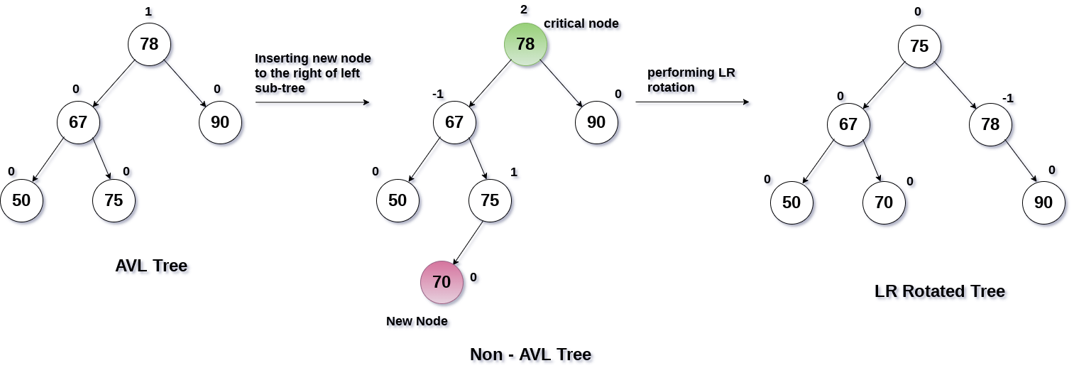
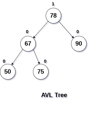
Insert the node with value 70 into the tree shown in the following data structure.
Solution
According to the property of binary search tree, the node with value 70 is inserted into the right of the left sub-tree of the root of tree.
As shown in the figure, the balance factor of the root node disturbed upon inserting 70 and this becomes the critical node A.
To rebalance the tree, LR rotation is to be performed. Node C i.e. 75 will become the new root node of the tree with B and A as its left and right child respectively.
Sub-trees T1, T2 become the left and right sub-tree of B while sub-trees T3, T4 become the left and right sub-tree of A.
The procedure is shown in the following figure.