Master-Slave JK Flip Flop
In “JK Flip Flop”, when both the inputs and CLK set to 1 for a long time, then Q output toggle until the CLK is 1. Thus, the uncertain or unreliable output produces. This problem is referred to as a race-round condition in JK flip-flop and avoided by ensuring that the CLK set to 1 only for a very short time.
Explanation
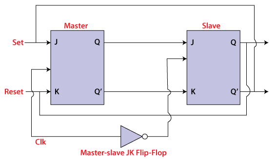
The master-slave flip flop is constructed by combining two JK flip flops. These flip flops are connected in a series configuration. In these two flip flops, the 1st flip flop work as “master”, called the master flip flop, and the 2nd work as a “slave”, called slave flip flop. The master-slave flip flop is designed in such a way that the output of the “master” flip flop is passed to both the inputs of the “slave” flip flop. The output of the “slave” flip flop is passed to inputs of the master flip flop.
In “master-slave flip flop”, apart from these two flip flops, an inverter or NOT gate is also used. For passing the inverted clock pulse to the “slave” flip flop, the inverter is connected to the clock’s pulse. In simple words, when CP set to false for “master”, then CP is set to true for “slave”, and when CP set to true for “master”, then CP is set to false for “slave”.
Working:
- When the clock pulse is true, the slave flip flop will be in the isolated state, and the system’s state may be affected by the J and K inputs. The “slave” remains isolated until the CP is 1. When the CP set to 0, the master flip-flop passes the information to the slave flip flop to obtain the output.
- The master flip flop responds first from the slave because the master flip flop is the positive level trigger, and the slave flip flop is the negative level trigger.
- The output Q’=1 of the master flip flop is passed to the slave flip flop as an input K when the input J set to 0 and K set to 1. The clock forces the slave flip flop to work as reset, and then the slave copies the master flip flop.
- When J=1, and K=0, the output Q=1 is passed to the J input of the slave. The clock’s negative transition sets the slave and copies the master.
- The master flip flop toggles on the clock’s positive transition when the inputs J and K set to 1. At that time, the slave flip flop toggles on the clock’s negative transition.
- The flip flop will be disabled, and Q remains unchanged when both the inputs of the JK flip flop set to 0.
Timing Diagram of a Master Flip Flop:
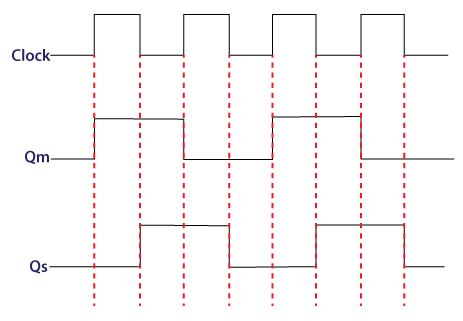
- When the clock pulse set to 1, the output of the master flip flop will be one until the clock input remains 0.
- When the clock pulse becomes high again, then the master’s output is 0, which will be set to 1 when the clock becomes one again.
- The master flip flop is operational when the clock pulse is 1. The slave’s output remains 0 until the clock is not set to 0 because the slave flip flop is not operational.
- The slave flip flop is operational when the clock pulse is 0. The output of the master remains one until the clock is not set to 0 again.
- Toggling occurs during the entire process because the output changes once in the cycle.