Multiprocessor Configuration Overview
Multiprocessor is the set of multiple processors that executes instructions simultaneously.
There are basically three configurations of multiprocessor:
- Coprocessor Configuration
- Closely Coupled Configuration
- Loosely Coupled Configuration
Coprocessor Configuration
A coprocessor performs the same task which the microprocessor performs. It is a specially designed circuit on microprocessor chip used to reduce the work load of the main processor. It shares the same memory, I/O system, bus, control logic and clock generator.
The coprocessor handles special task like mathematical calculations, graphical display on screen etc.
Intel 8086 and 8087 cannot perform complex mathematical operations, so in these cases, the microprocessor requires the math coprocessor like Intel 8087 math coprocessor, which can easily perform complex mathematical operations very quickly.
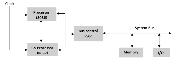
Fig: Block Diagram of Coprocessor configuration
Connection between processor and coprocessor - The processor and coprocessor are connected via RQ-/GT-, TEST, QS0 and QS1 signals.
- TEST signal is connected to BUSY pin of coprocessor and the remaining 3 pins are connected to the same pins of the coprocessor.
- RQ-/GT- : This signal is used for the arbitration of bus.
- QS0 and QS1: These are used to track the status of the queue of the host processor.
- TEST: This signal is used to take care of the coprocessor?s activity i.e. the coprocessor is idle or busy.
Closely Coupled Configuration
Closely coupled configuration is exactly similar to the coprocessor configuration. Like coprocessor, it also shares the same memory, I/O system bus, and control logic and control generator with the host processor.
However, the host processor and the coprocessor fetch and execute their own instructions. The system bus is handled by the coprocessor and the host processor independently.
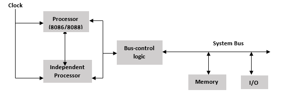
Fig: Block diagram of closely coupled configuration
How are the processor and independent processor connected? - Memory space is used to provide the connection between independent processor and host processor.
- It does not use any instructions like WAIT, ESC etc. for communication.
- The host processor sends the commands to the ports for managing the memory and for waking up the independent processor.
- The independent processor accesses the memory and executes the task.
- When the task has been completed, it sends an acknowledgement to the host processor by using the status signal or an interrupt request.
Loosely Coupled Configuration
A loosely coupled multiprocessor configuration consists of the number of modules of the microprocessor based systems, which are connected through a common system bus. Each module of this configuration consists of their own clock generator, memory, I/O devices and is connected through a local bus.
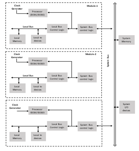
Fig: Block Diagram of loosely coupled configuration
8087 Numeric Data Processor
8087 numeric data processor is also known as Math Co-Processor, Floating point unit or Numeric processor extension.
It was first designed by Intel to pair with 8086/8088 resulting in easier and faster calculations.
Once the instructions are identified by the 8086/8088 processor, then it is sent to the 8087 co-processor for further execution.
The data types supported by Intel 8087 are:
- Binary integers
- Packed decimal numbers
- Real numbers
- Temporary real format
Features of 8087 numeric data processor
- It supports different data types like integer, float, and real types ranging from 2-10 bytes.
- It follows IEEE floating point standards.
- The processing speed is so high.
8087 Architecture
- 8087 architecture is divided into two group i.e.
- Control Unit (CU)
- Numeric Extension Unit (NEU)
- The Control Unit is responsible for all the communication between the processor and the memory such as it reads and writes memory operands, receives and decodes instructions, maintains parallel queue, etc.
- The Numeric Extension Unit (NEU) is responsible for all the numeric processor instructions like arithmetic, logical, transcendental, and data transfer instructions. It has 8 register stacks, which holds the operands for instructions and their results.
- CU and NEU works asynchronously with each other.
- Intel 8087 uses QS0 and QS1 pins to obtain and identify the instructions fetched by the host CPU.
- All the coprocessor instructions are identified by Escape (ESC) instructions code bits i.e. they start with ‘F’. The coprocessor only executes the Escape instructions while other instructions are executed by the microprocessor.
- Once CPU recognizes ESC code, it triggers the execution of the numeric processor instruction in 8087.
- While executing, the ESC code identifies the coprocessor instruction that require memory operand or not. If the CPU does not require any memory operand, it will directly execute otherwise physical address of the operand is calculated using any one of the addressing modes allowed in 8086 and 1 dummy read cycle is initiated by the CPU.
- Then 8087 is ready with execution outputs, CU gets the control of bus from 8086 and executes a write cycle to write the outputs in the memory at the pre specialized address.
- Microcode control unit generates control signals required for execution of the instruction.
- Programmable shifter is used to shift the operands during the execution of instructions like FMUL and FDIV.
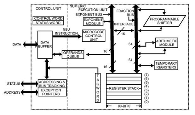
Fig: Architecture of 8087 Coprocessor
8087 Pin Description
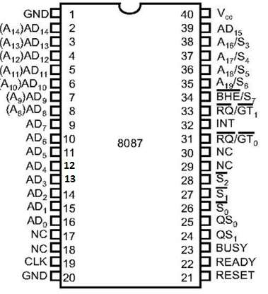
Fig: Pin diagram of Intel 8087
- AD0 – AD15: These are time multiplexed address/data lines, which carry addresses during T1 clock cycle and data during T2, T3, Tw and T4 clock cycles.
- A19/S6 – A16/S3: These are the time multiplexed address/status lines. These functions are similar to the pins of Intel 8086.
- BHE/S7: During the first clock cycle, it is used to enable data on to the higher byte of the 8086 data bus and after that during T2, T3, Tw and T4 clock cycles, it works as status line S7.
- QS1 – QS0: These are queue status input signal which is responsible for status of instruction queue.
Conditions of QS1 – QS0 are given below:
| QS0 | QS1 | Status |
|---|---|---|
| 0 | 0 | No operation |
| 0 | 1 | 1st byte of opcode from the queue |
| 1 | 0 | Empty the queue |
| 1 | 1 | Subsequent byte from the queue |
- INT: It is an interrupt signal used to indicate an unmasked exception has been received during the execution.
- BUSY (Output): When BUSY signal high then it indicates a busy state to the CPU.
- READY (input): This signal is used to reject the internal activities of the coprocessor and prepare it for further execution whenever required by the CPU.
- S0, S1, S2: These are the status signals which gives the status of the operation which is used by the Bus Controller 8087 to generate memory and I/O control signals.
| S2 | S1 | S0 | Status |
|---|---|---|---|
| 0 | X | X | Unused |
| 1 | 0 | 0 | Unused |
| 1 | 0 | 1 | Memory Read |
| 1 | 1 | 0 | Memory Write |
| 1 | 1 | 1 | Passive |
- RQ/GT1 and RQ/GT0: These are Request/Grant signals used by the 8087 processors to get the control of the bus from the host processor 8086/8088 for operand transfers.
- CLK (input): This input gives the basic timings for the processor operation.
- VCC: Power supply +5V.