Sequence Diagram
The sequence diagram represents the flow of messages in the system and is also termed as an event diagram. It helps in envisioning several dynamic scenarios. It portrays the communication between any two lifelines as a time-ordered sequence of events, such that these lifelines took part at the run time. In UML, the lifeline is represented by a vertical bar, whereas the message flow is represented by a vertical dotted line that extends across the bottom of the page. It incorporates the iterations as well as branching.
Purpose of a Sequence Diagram
- To model high-level interaction among active objects within a system.
- To model interaction among objects inside a collaboration realizing a use case.
- It either models generic interactions or some certain instances of interaction.
Notations of a Sequence Diagram
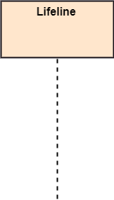
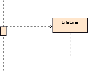
Lifeline
An individual participant in the sequence diagram is represented by a lifeline. It is positioned at the top of the diagram.
Actor
A role played by an entity that interacts with the subject is called as an actor. It is out of the scope of the system. It represents the role, which involves human users and external hardware or subjects. An actor may or may not represent a physical entity, but it purely depicts the role of an entity. Several distinct roles can be played by an actor or vice versa.

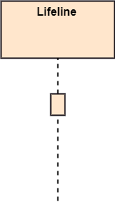
Activation
It is represented by a thin rectangle on the lifeline. It describes that time period in which an operation is performed by an element, such that the top and the bottom of the rectangle is associated with the initiation and the completion time, each respectively.
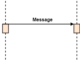
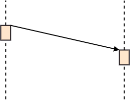
Messages
The messages depict the interaction between the objects and are represented by arrows. They are in the sequential order on the lifeline. The core of the sequence diagram is formed by messages and lifelines.
Following are types of messages enlisted below:
- Call Message: It defines a particular communication between the lifelines of an interaction, which represents that the target lifeline has invoked an operation.

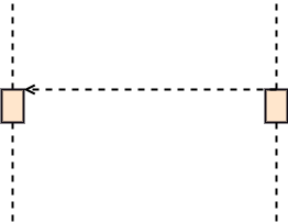
- Return Message: It defines a particular communication between the lifelines of interaction that represent the flow of information from the receiver of the corresponding caller message.
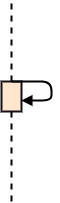
- Self Message: It describes a communication, particularly between the lifelines of an interaction that represents a message of the same lifeline, has been invoked.
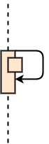
- Recursive Message: A self message sent for recursive purpose is called a recursive message. In other words, it can be said that the recursive message is a special case of the self message as it represents the recursive calls.
- Create Message: It describes a communication, particularly between the lifelines of an interaction describing that the target (lifeline) has been instantiated.
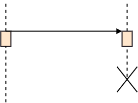
- Destroy Message: It describes a communication, particularly between the lifelines of an interaction that depicts a request to destroy the lifecycle of the target.
- Duration Message: It describes a communication particularly between the lifelines of an interaction, which portrays the time passage of the message while modeling a system.
Note
A note is the capability of attaching several remarks to the element. It basically carries useful information for the modelers.

Sequence Fragments
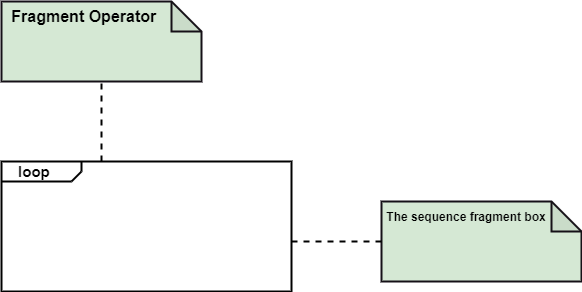
- Sequence fragments have been introduced by UML 2.0, which makes it quite easy for the creation and maintenance of an accurate sequence diagram.
- It is represented by a box called a combined fragment, encloses a part of interaction inside a sequence diagram.
- The type of fragment is shown by a fragment operator.
Types of fragments
Following are the types of fragments enlisted below;
| Operator | Fragment Type |
|---|---|
| alt | Alternative multiple fragments: The only fragment for which the condition is true, will execute. |
| opt | Optional: If the supplied condition is true, only then the fragments will execute. It is similar to alt with only one trace. |
| par | Parallel: Parallel executes fragments. |
| loop | Loop: Fragments are run multiple times, and the basis of interaction is shown by the guard. |
| region | Critical region: Only one thread can execute a fragment at once. |
| neg | Negative: A worthless communication is shown by the fragment. |
| ref | Reference: An interaction portrayed in another diagram. In this, a frame is drawn so as to cover the lifelines involved in the communication. The parameter and return value can be explained. |
| sd | Sequence Diagram: It is used to surround the whole sequence diagram. |
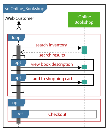
Example of a Sequence Diagram
An example of a high-level sequence diagram for online bookshop is given below.
Any online customer can search for a book catalog, view a description of a particular book, add a book to its shopping cart, and do checkout.
Benefits of a Sequence Diagram
- It explores the real-time application.
- It depicts the message flow between the different objects.
- It has easy maintenance.
- It is easy to generate.
- Implement both forward and reverse engineering.
- It can easily update as per the new change in the system.
The drawback of a Sequence Diagram
- In the case of too many lifelines, the sequence diagram can get more complex.
- The incorrect result may be produced, if the order of the flow of messages changes.
- Since each sequence needs distinct notations for its representation, it may make the diagram more complex.
- The type of sequence is decided by the type of message.