D Flip-Flop
A D flip-flop is a sequential element that follows the input pin d at the clock’s given edge. D flip-flop is a fundamental component in digital logic circuits.
There are two types of D Flip-Flops being implemented: Rising-Edge D Flip Flop and Falling-Edge D Flip Flop.
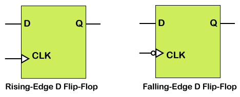
D flip flop is an edge-triggered memory device that transfers a signal’s value on its D input to its Q output when an active edge transition occurs on its clock input. Then, the output value is held until the next active clock cycle.
Flip flops are inferred using the edge triggered always statements. The always statement is edge-triggered by including either a posedge or negedge clause in the event list. Here are some examples of sequential always statements, such as:
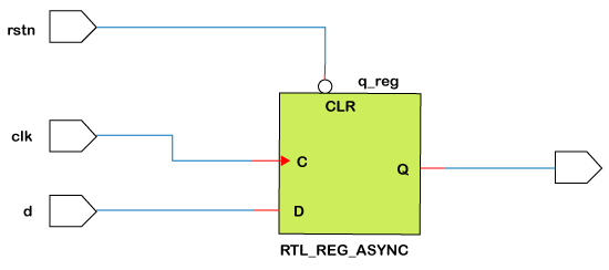
If an asynchronously reset flip flop is being modeled, a second posedge or negedge clause is needed in the event list of the always statement. Also, most synthesis tools require that the reset must be used in if statement directly following the always statement, or after begin if it is in a sequential begin-end block.
Example
Design 1: With the async active-low reset
Hardware Schematic
Testbench
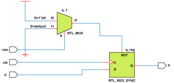
Design 2: With sync active-low reset
Hardware Schematic
Testbench