Verilog Ports
Port is an essential component of the Verilog module. Ports are used to communicate for a module with the external world through input and output.
It communicates with the chip through its pins because of a module as a fabricated chip placed on a PCB.
Every port in the port list must be declared as input, output or inout. All ports declared as one of them is assumed to be wire by default to declare it, or else it is necessary to declare it again.
Ports, also referred to as pins or terminals, are used when wiring the module to other modules.
- If the module does not exchange any signals with the environment, there are no ports in the list.
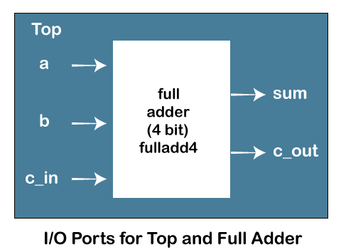
- Consider a 4-bit full adder that is instantiated inside a top-level module.
- The module fulladd4 takes input on ports a, b, and c_in and produces an output on ports sum and c_out.
Port Declaration
Each port in the port list is defined as input, output, or inout based on the port signal’s direction.
If a port declaration includes the net or variable types, then that port is considered completely declared. It is illegal to declare the same port in a net or variable type declaration.
And if the port declaration does not include a net or variable type, then the port can be declared again in a net or variable type declaration.
For example, consider the ports for top and full adder shown in the above image.
NOTE: By convention, outputs of the module are always first in the port list. This convention is also used in the predefined modules in Verilog.
Wire and Reg
In Verilog, all port declarations are implicitly declared as wire. If a port is intended to be a wire, it is sufficient to declare it as output, input, or inout.
Input and inout ports are generally declared as wires. However, if output ports hold their value, they must be declared as reg as shown below:
NOTE: Ports of the type input and inout cannot be declared as reg.
Port Connection Rules
There are two methods of making connections between signals specified in the module instantiation and the ports in a module definition.
1. Connecting by ordered list: It is the simple method for beginners. The signals to be connected must appear in the module instantiation in the same order as the ports in the module definition.
2. Connecting ports by name: For large designs where modules have approx 50 ports or above. In this situation, remembering the order of the ports in the module definition is complicated and impractical.
Verilog provides the capability to connect external signals to ports by the port names, rather than by position.
Another main reason for connecting ports by name is that as long as the port name is not changed, the order of ports in the port list of a module can be rearranged without changing the port connections in module instantiations.
Ports Variations
- Verilog has undergone a few research, and the original IEEE version in 1995 had the following way for port declaration.
Here the module declaration had to first list of the names of ports within the brackets. And then the direction of those ports defined later within the body of the module.
- ANSI-C style port naming was introduced in 2001. It allowed the type to be specified inside the port list.