AutoCAD Table
The table command in AutoCAD is used to insert the table containing rows and columns. We can resize the rows and columns, and can also stretch the entire table.
We can insert the appropriate data in rows and columns according to the requirements.
Note: Tables in AutoCAD do not support annotative scaling.
Let’s implement a table in AutoCAD.
The steps are listed below:
1. Type TABLE on the command line or command prompt and press Enter.
2. A dialog box will appear, a shown below:
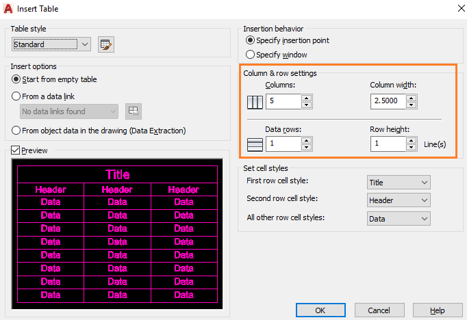
Let’s discuss the parameters of the above window.
- Specify Insertion point- The upper-left corner of the table is specified as an insertion point on the display. The insertion point is placed on the display either by the pointing device or specifying the coordinate value on the command line.
- Specify window- It specifies the location and size of the table. The point is placed on the display either by the pointing device or specifying the coordinate value on the command line. The column width and data rows depend on the column, row, and size of window settings.
- Column and Row Settings- We are required to specify the value in the columns, column width, data rows, and row height The table will be created based on the specified criteria.
- Set cell styles- We can adjust the cell styles according to the requirements.
3. Specify the columns, column width, data rows, and row height, as shown in above image.
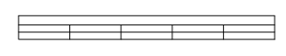
4. Click on the OK button at the bottom.
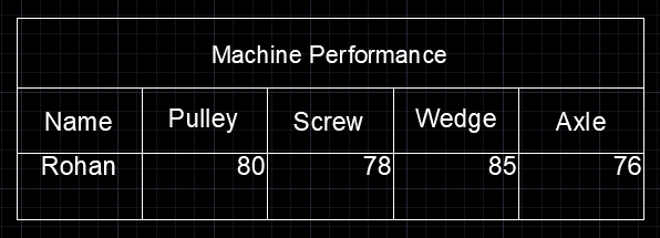
The table will appear as:
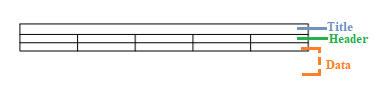
Here,
1st and 2nd rows are the Title and Header. The row after the 2nd row will be the specified rows. Since, we have specified only 1 row; the total rows will be 3, as shown below:
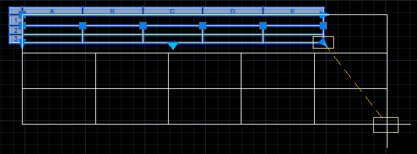
5. To modify the shape and size of the created table, click on the table, as shown below:
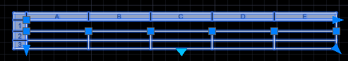
Select the blue triangle and drag the triangle to the desired position, as shown below:
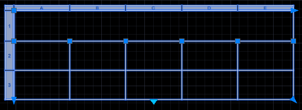
6. Press Enter.
The table will now appear as:
7. We can also align the grips of the table using the object snap tracking.
Adding Information to the created table
After creating the table, we are required to insert text inside the table.
Here, we can also perform calculations inside the table.
Let’s discuss this in detail.
8. Double-click on each cell.
9. Write the text, as shown below:
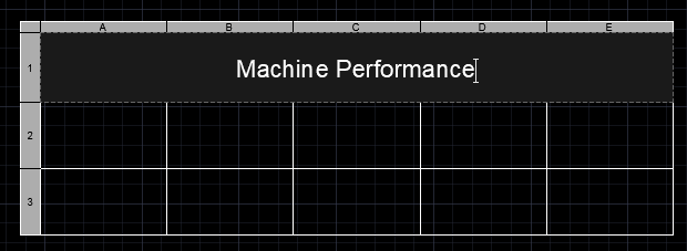
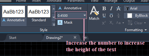
We can modify the size of the text, which is present on the top of the display, as shown below:
10. Continue writing on other blocks by clicking.
The table will now appear as:
Data Format
11. To change the data format of the table, click on the cell
12. A dialog box will appear, as shown below:
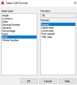
Here, we can change the format of the cell according to the requirements.
Arithmetic Operations
We can also perform arithmetic operations, such as addition, multiplication, etc. in the table.
Let’s perform the addition.
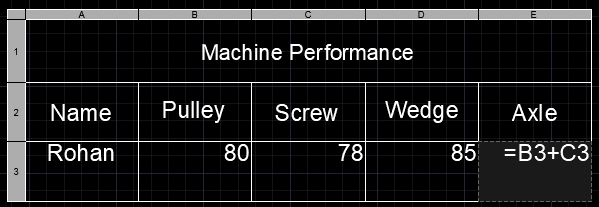
13. Write (=B3 + C3) on the cell. The formula should be written in the particular cell to produce the output on that cell.
It is shown below:
14. The output is shown below:
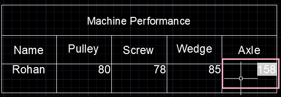
15. Similarly, for multiplication, we are required to use * symbol instead of +.
16. We can also perform other operations.