ADC0804 Interfacing with AVR Microcontroller
ADC0804 Pin-out and Typical Connections:
For interfacing the ADC0804 with any microcontroller a minimum of 11 pins is required of Analog to Digital Converter for interfacing it with the microcontroller. Out of 11 pins of ADC0804 8 pins are used as data pins and 3 pins are used as control pins.
As shown in the below circuit chip select pin can be made low if we are not using the microcontroller port for any other peripheral multiplexing.
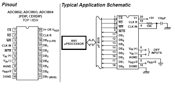
For using the Integrated Circuit (IC) the universal rule is used. All we need to study the datasheet of the IC which shows how to send a data, which signal to send and at what time the signal must be made low or high etc.
Note: Whenever you are working with an IC and wanted to know how to communicate with that IC then simply look into a timing diagram of that IC from its datasheet. It gives you the complete information regarding the communication of IC.
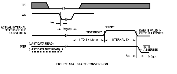
The start conversion timing diagram is shown below:
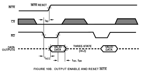
The end of conversion timing diagram is shown below:
The above timing diagrams are from ADC0804 datasheet. The first diagram in FIGURE 10A represents how to start a conversion. Using timing diagram you can see which signal is to be asserted and at what time we need to start a conversion.
Below mention steps are used for starting an Analog to Digital Conversion process:
- Configure chip select (CS) signal as low.
- Configure write (WR) signal low.
- Configure chip select (CS) high.
- Wait until INTR pin to go low (means conversion ends).
Once the conversion process in ADC is complete, the data is available inside the output latch of the ADC. The FIGURE 10B shows a timing diagram of how to read the converted value from the output latch process of ADC. Data of new conversion process is available for reading after ADC0804 make INTR pin lows when the conversion is over.
Below mention steps are used for reading the output from the ADC0804:
- Configure chip select (CS) pin as low.
- Configure read (RD) signal low.
- Read the data from a port where ADC is connected.
- Configure read (RD) signal high.
- Configure chip select (CS) signal high.
The AVR C program for ADC0804 is given below: