Binary Adder
The registers play an important role in performing the micro-operations. The registers hold the digital component and the data which performs the arithmetic operation. The Binary Adder is a logical circuit which is used to perform the addition operation of two binary number of any length.
The Binary Adder is formed with the help of the Full-Adder circuit. The Full-Adders are connected in series, and the output carry of the first Adder will be treated as the input carry of the next Full-Adder.
N-Bit Parallel Adder
The Full Adder is used to sum two single-bit binary numbers with carry input. In digital calculation, we need to add two n-bit binary numbers rather than only single-bit binary numbers. For this purpose, we need to use n-bit parallel Adder. In order to get N-bit parallel adder, we cascade the n number of Full Adders. The carry output of the first Adder is treated as the carry input of the second Adder.
4-bit Binary Adder
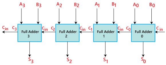
- The ‘A’ and ‘B’ are the augend, and addend bits are defined by the subscript numbers. The subscripts start from right to left, and the lower-order bit is defined by subscript ‘0’.
- The C0, C1, C2, and C3 are the carry inputs which are connected together as a chain using Full Adder. The C4 is the carry output produced by the last Full-Adder.
- The Cout of the first Adder is connected as the Cin of the next Full-Adder.
- The S0, S1, S2, and S3 are the sum outputs that produce the sum of augend and addend bits.
- The inputs for the input variable ‘A’ and ‘B’ are fetched from different source registers. For example, the bit for the input variable ‘A’ comes from register ‘R1’, and a bit for the input variable ‘B’ comes from register ‘R2’.
- The outcome produced by adding both input variables is stored into either third register or to one of the source registers.