Half Subtractor
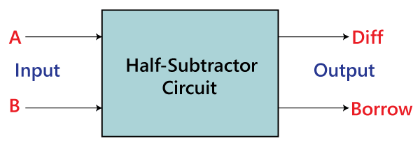
The half subtractor is also a building block for subtracting two binary numbers. It has two inputs and two outputs. This circuit is used to subtract two single bit binary numbers A and B. The ‘diff‘ and ‘borrow’ are two output states of the half subtractor.
Block diagram
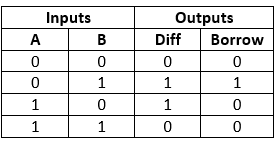
Truth Table
The SOP form of the Diff and Borrow is as follows:
Diff= A’B+AB’
Borrow = A’B
In the above table,
- ‘A’ and ‘B’ are the input variables whose values are going to be subtracted.
- The ‘Diff’ and ‘Borrow’ are the variables whose values define the subtraction result, i.e., difference and borrow.
- The first two rows and the last row, the difference is 1, but the ‘Borrow’ variable is 0.
- The third row is different from the remaining one. When we subtract the bit 1 from the bit 0, the borrow bit is produced.
Construction of Half Subtractor Circuit
In the block diagram, we have seen that it contains two inputs and two outputs. The carry and sum are the output states of the half subtractor. The half subtractor is designed with the help of the following logic gates:
- 2-input AND gate.
- 2-input Exclusive-OR Gate or Ex-OR Gate
- NOT or inverter Gate
1. 2-input Exclusive-OR Gate or Ex-OR Gate
The Diff bit is generated with the help of the Exclusive-OR or Ex-OR gate.
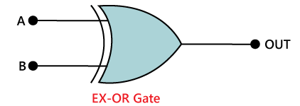
The above is the symbol of the EX-OR gate. In the above diagram, ‘A’ and ‘B’ are the inputs, and ‘Diff’ is the final outcome after performing the XOR operation of both numbers.
The truth table of the EX-OR gate is as follows:
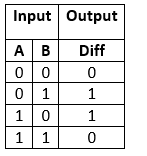
From the above table, it is clear that the XOR gate gives the result 1 when both of the inputs are different. When both of the inputs are the same, the XOR gives the result 0. To learn more about the XOR gate, click here.
2. 2-input AND gate:
The XOR gate is unable to generate the carry bit. For this purpose, we use another gate called AND gate. The AND gate is not enough to give the correct result of ‘Borrow’. We will use the NOT gate with the ‘AND’ gate to get the correct result.
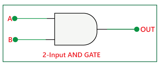
The above is the symbol of the AND gate. In the above diagram, ‘A’ and ‘B’ are the inputs, and ‘OUT’ is the final outcome after performing AND operation of both numbers.
There is the following truth table of AND gate:
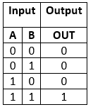
From the above table, it is clear that the AND gate gives the result 1 when both of the inputs are 1. When both of the inputs are different and 0, the AND gates gives the result 0. To learn more about the AND gate, click here.
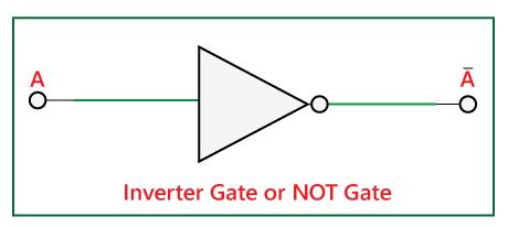
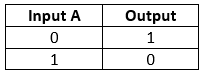
3. NOT or Inverter Gate:
The NOT gate is used to get the inverse output. We can combine the ‘AND’ and ‘NOT’ gates in order to get the combinational gate ‘NAND’. By inverting the input ‘A’ using ‘NOT’ gate and then use the output of the ‘NOT’ gate as the input of the ‘AND’ gate, we can get the ‘Borrow’ bit.
Half-Subtractor logical circuit
So, the Half Subtractor is designed by combining the ‘XOR’, ‘AND’, and ‘NOT’ gates and provide the Diff and Borrow.

The Boolean expression of the Half Adder circuit is given below:
Diff= A XOR B (A⊕B)
Borrow= not-A AND B (A’.B)