UML-Building Blocks
UML is composed of three main building blocks, i.e., things, relationships, and diagrams. Building blocks generate one complete UML model diagram by rotating around several different blocks. It plays an essential role in developing UML diagrams. The basic UML building blocks are enlisted below:
- Things
- Relationships
- Diagrams
Things
Anything that is a real world entity or object is termed as things. It can be divided into several different categories:
- Structural things
- Behavioral things
- Grouping things
- Annotational things
Structural things
Nouns that depicts the static behavior of a model is termed as structural things. They display the physical and conceptual components. They include class, object, interface, node, collaboration, component, and a use case.
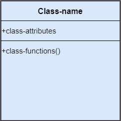
Class: A Class is a set of identical things that outlines the functionality and properties of an object. It also represents the abstract class whose functionalities are not defined. Its notation is as follows;
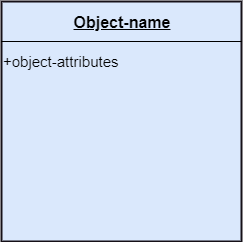
Object:: An individual that describes the behavior and the functions of a system. The notation of the object is similar to that of the class; the only difference is that the object name is always underlined and its notation is given below;
Interface: A set of operations that describes the functionality of a class, which is implemented whenever an interface is implemented.
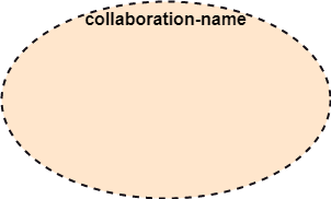
Collaboration: It represents the interaction between things that is done to meet the goal. It is symbolized as a dotted ellipse with its name written inside it.
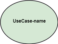
Use case: Use case is the core concept of object-oriented modeling. It portrays a set of actions executed by a system to achieve the goal.
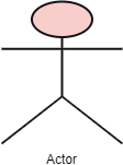
Actor: It comes under the use case diagrams. It is an object that interacts with the system, for example, a user.
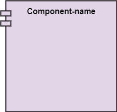
Component: It represents the physical part of the system.
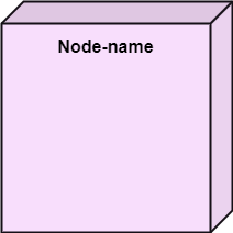
Node: A physical element that exists at run time.
Behavioral Things
They are the verbs that encompass the dynamic parts of a model. It depicts the behavior of a system. They involve state machine, activity diagram, interaction diagram, grouping things, annotation things
State Machine: It defines a sequence of states that an entity goes through in the software development lifecycle. It keeps a record of several distinct states of a system component.
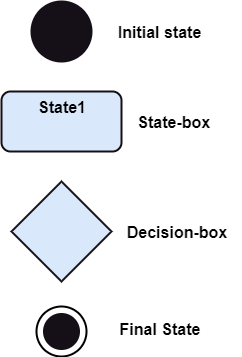
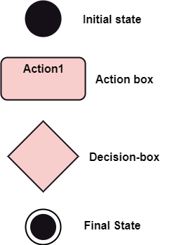
Activity Diagram: It portrays all the activities accomplished by different entities of a system. It is represented the same as that of a state machine diagram. It consists of an initial state, final state, a decision box, and an action notation.
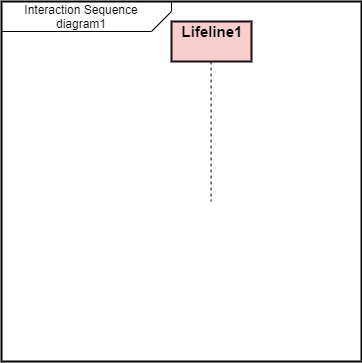
Interaction Diagram: It is used to envision the flow of messages between several components in a system.
Grouping Things
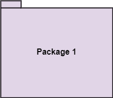
It is a method that together binds the elements of the UML model. In UML, the package is the only thing, which is used for grouping.
Package: Package is the only thing that is available for grouping behavioral and structural things.
Annotation Things
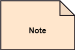
It is a mechanism that captures the remarks, descriptions, and comments of UML model elements. In UML, a note is the only Annotational thing.
Note: It is used to attach the constraints, comments, and rules to the elements of the model. It is a kind of yellow sticky note.
Relationships
It illustrates the meaningful connections between things. It shows the association between the entities and defines the functionality of an application. There are four types of relationships given below:
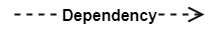
Dependency: Dependency is a kind of relationship in which a change in target element affects the source element, or simply we can say the source element is dependent on the target element. It is one of the most important notations in UML. It depicts the dependency from one entity to another.
It is denoted by a dotted line followed by an arrow at one side as shown below,
Association: A set of links that associates the entities to the UML model. It tells how many elements are actually taking part in forming that relationship.
It is denoted by a dotted line with arrowheads on both sides to describe the relationship with the element on both sides.

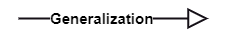
Generalization: It portrays the relationship between a general thing (a parent class or superclass) and a specific kind of that thing (a child class or subclass). It is used to describe the concept of inheritance.
It is denoted by a straight line followed by an empty arrowhead at one side.
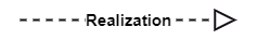
Realization: It is a semantic kind of relationship between two things, where one defines the behavior to be carried out, and the other one implements the mentioned behavior. It exists in interfaces.
It is denoted by a dotted line with an empty arrowhead at one side.
Diagrams
The diagrams are the graphical implementation of the models that incorporate symbols and text. Each symbol has a different meaning in the context of the UML diagram. There are thirteen different types of UML diagrams that are available in UML 2.0, such that each diagram has its own set of a symbol. And each diagram manifests a different dimension, perspective, and view of the system.
UML diagrams are classified into three categories that are given below:
- Structural Diagram
- Behavioral Diagram
- Interaction Diagram
Structural Diagram: It represents the static view of a system by portraying the structure of a system. It shows several objects residing in the system. Following are the structural diagrams given below:
- Class diagram
- Object diagram
- Package diagram
- Component diagram
- Deployment diagram
Behavioral Diagram: It depicts the behavioral features of a system. It deals with dynamic parts of the system. It encompasses the following diagrams:
- Activity diagram
- State machine diagram
- Use case diagram
Interaction diagram: It is a subset of behavioral diagrams. It depicts the interaction between two objects and the data flow between them. Following are the several interaction diagrams in UML:
- Timing diagram
- Sequence diagram
- Collaboration diagram