Construction of Single – Phase Transformers
A single-Phase transformer consists of primary and secondary winding. The core of the transformer is made of thin sheets (called laminations) of high grade of silicon. These laminations are provided in the transformer to reduce eddy-current loss, and the silicon steel reduces hysteresis loss. The laminations present in the transformer are insulated from one another by heat resistant enamel coating. L – Type and E- type laminations are used for constructions.
There are two basic types of transformer constructions:
- Core type construction.
- Shell type construction.
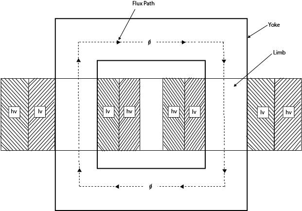
Core type Construction
In the core type transformer, the magnetic circuit consists of two vertical legs or limbs with two horizontal sections, called yokes. To minimize the leakage flux, half of each winding is placed on each leg of the core. The low voltage winding is placed next to the core, and the high voltage winding is placed around the low voltage winding to reduce the insulating material required. Thus, the two winding are arranged as concentric coils. Such type of winding is called as concentric winding or cylindrical winding.
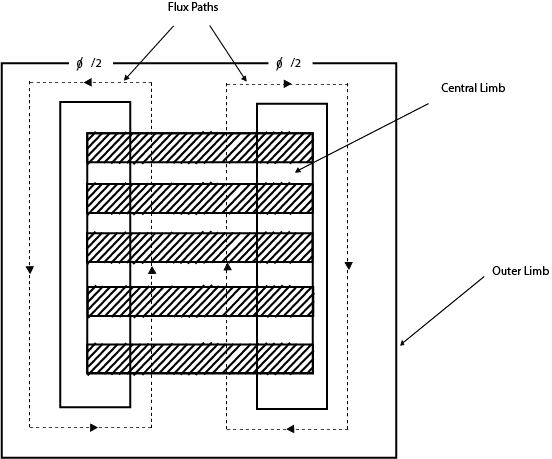
Shell type Construction
In the shell type transformer, both the primary and secondary winding are wounded on the central limb, and the low reluctance path is completed by the outer limbs. Each winding is subdivided into sections. Low voltage (lv) and High voltage (hv) subsections are alternatively placed in the form of sandwich that is why this winding is also called sandwich or disc winding.
The core is made up of two types of laminations. The laminations for the core type are U, and I shaped. Firstly the U- shaped laminations are stacked together for the required length. Half of the prewound low voltage coil is placed around the limbs. The lv coil is further provided with insulation. Then half of the prewound hv coil is placed around the lv coil. The core is then closed by the I-shaped laminations at the top.
Ideal Transformer
An Ideal transformer is an imaginary transformer which has the following properties:
- Its primary and secondary winding resistances are negligible.
- The core has infinite permeability (µ) so that negligible mmf is required to establish the flux in the core.
- Its leakage flux and leakage inductances are zero. The entire flux is confined to the core and links both windings.
- There are no losses due to resistance, hysteresis and eddy currents. Thus, the efficiency is 100 percent.

Figure: Ideal iron-core transformer
The transformer that has zero primary and zero secondary impedance, is called an ideal transformer. The applied voltage V1 in the primary is equal to the induced voltage E1. Similarly, the induced voltage E2 is equal to the output voltage V2 of the secondary.

Figure: No-load Phasor diagram of an ideal transformer.
Then,
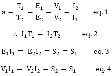
The equation-2 states that the demagnetizing, ampere-turns of the secondary are equal and opposite to the magnetizing mmf of the primary of an Ideal transformer.
Applications of Transformers
- The level of voltage and current can be changed in electrical power systems.
- Transformer known as instrument transformer is used to measure the voltage and current.
- In combined ac/dc power systems, the transformers are used to convert hvac to hvdc.
- To isolate one circuit from another, since primary and secondary are not connected.