Latches
A Latch is a special type of logical circuit. The latches have low and high two stable states. Due to these states, latches also refer to as bistable-multivibrators. A latch is a storage device that holds the data using the feedback lane. The latch stores 1 -bit until the device set to 1. The latch changes the stored data and constantly trials the inputs when the enable input set to 1.
Based on the enable signal, the circuit works in two states. When the enable input is high, then both the inputs are low, and when the enable input is low, both the inputs are high.
Types of Latches
There are various types of latches used in digital circuits which are as follows:
- SR Latch
- Gated S-R Latch
- D latch
- Gated D Latch
- JK Latch
- T Latch.
SR Latch
The SR latch is a special type of asynchronous device which works separately for control signals. It depends on the S-states and R-inputs. The SR latch design by connecting two NOR gates with a cross loop connection. The SR latch can also be designed using the NAND gate. Below are the circuit diagram and the truth table of the SR latch.
Truth Table
| S | R | Q | Q’ |
|---|---|---|---|
| 0 | 0 | latch | Latch |
| 0 | 1 | 0 | 1 |
| 1 | 0 | 1 | 0 |
| 1 | 1 | 0 | 0 |
Circuit Diagram 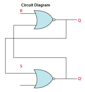
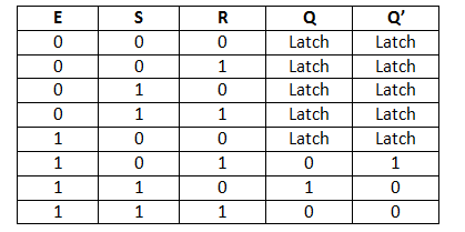
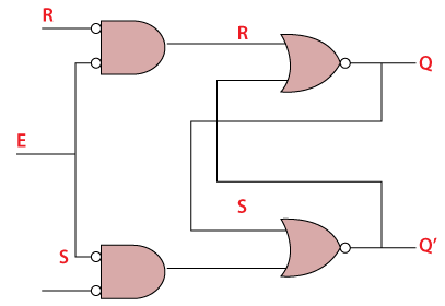
Gated SR Latch
A Gated SR Latch is a special type of SR Latch having three inputs, i.e., Set, Reset, and Enable. The enable input must be active for the SET and RESET inputs to be effective.The ENABLE input of gated SR Latch enables the operation of the SET and RESET inputs.This ENABLE input connects with a switch. The Set-Reset inputs are enabled when this switch is on. Otherwise, all the changes are ignored in the set and reset inputs. Below are the circuit diagram and the truth table of the Gated SR latch.
Truth Table
Circuit Diagram
D Latch
The D latch is the same as D flip flop. The only difference between these two is the ENABLE input. The output of the latch is the same as the input passed to the Data input when the ENABLE input set to 1. At that time, the latch is open, and the path is transparent from input to output. If the ENABLE input is set to 0, the D latch’s output is the last value of the latch, i.e., independent from the input D, and the latch is closed. Below are the circuit diagram and the truth table of the D latch.
Truth Table 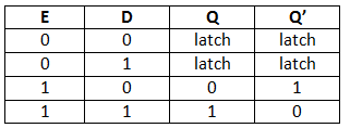
Circuit Diagram
Gated D Latch
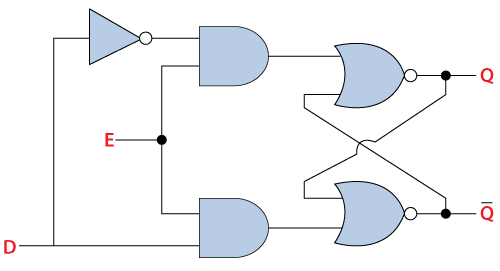
The Gated D Latch is another special type of gated latch having two inputs, i.e., DATA and ENABLE. When the enable input set to 1, the input is the same as the Data input. Otherwise, there is no change in output.
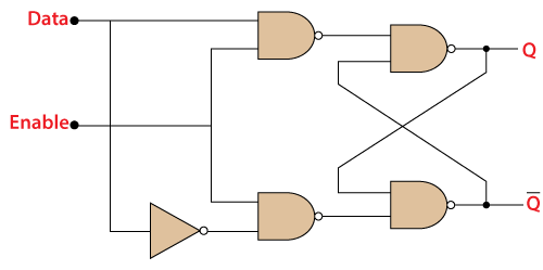
We can design the gated D latch by using gated SR latch. The set and reset inputs are connected together using an inverter. By doing this, the outputs will be opposite to each other. Below is the circuit diagram of the Gated D latch.
Circuit Diagram
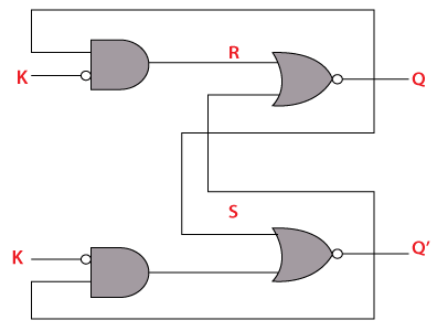
JK Latch
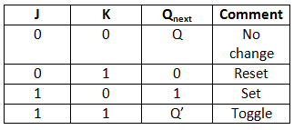
The JK Latch is the same as the SR Latch. In JK latch, the unclear states are removed, and the output is toggled when the JK inputs are high. The only difference between SR latch JK latches is that there is no output feedback towards the inputs in the SR latch, but it is present in the JK latch. The circuit diagram and truth table of the JK latch are as follows:
Truth Table
Circuit Diagram
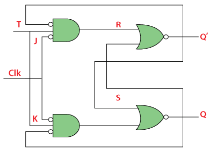
T Latch
The T latch forms by shorting the JK latch inputs. The output of the T latch toggle when the input set to 1 or high. Below is the circuit diagram of the T latch.
Circuit Diagram