Verilog Module
A module is a block of Verilog code that implements certain functionality. Modules can be embedded within other modules, and a higher level module can communicate with its lower-level modules using their input and output ports.
Syntax
A module should be enclosed within a module and endmodule keywords. The name of the module should be given right after the module keyword, and an optional list of ports may be declared as well.
Note: The ports declared in the list of port declarations cannot be re-declared within the module’s body.
All variable declarations, functions, tasks, dataflow statements, and lower module instances must be defined within the module and endmodule keywords.
Purpose of a Module
A module represents a design unit that implements specific behavioral characteristics and will get converted into a digital circuit during synthesis.
Any combination of inputs can be given to the module, and it will provide a corresponding output.
It allows the same module to be reused to form more significant modules that implement more complex hardware.
Hardware Schematic
Instead of building up smaller blocks to form bigger design blocks, the reverse process can also be done.
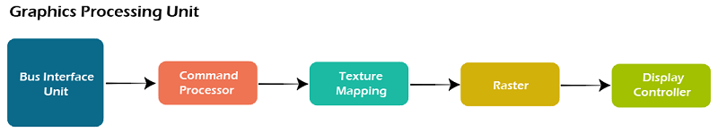
Consider the breakdown of a simple GPU engine into smaller components such that each can be represented as a module that implements a specific feature.
The below GPU engine is divided into five different sub-blocks where each performs a specific functionality.
The bus interface unit gets data from outside into the design, which gets processed by another unit to instructions extraction. Other units down the line process data provided by the previous unit.
Each sub-block can be represented as a module with a specific set of input and output signals for communication with other modules, and each sub-block can be further divided into more sub-sub-blocks as required.
Top-level Modules
A top-level module is one that contains all other modules. A top-level module is not instantiated within any other module.
For example, design modules are usually instantiated within top-level testbench modules so that simulation can be run by providing input stimulus.
But, the testbench is not instantiated within any other module because it is a block that encapsulates everything else.
1. Design Top Level
The design code shown below has a top-level module called design. It contains all other sub-modules required to make the design complete.
The sub-module can have a more nested sub-module, such as mod3 inside mod1 and mod4 inside mod2.
2. Testbench Top Level
The testbench module contains a stimulus to check the functionality of the design and primarily used for functional verification by using simulation tools.
Hence the design is instantiated and called d0 inside the testbench module. The testbench is the top-level module from a simulator perspective.
Hierarchical Names
A hierarchical structure is formed when modules can be instantiated inside one another, and hence the top-level module is called the root.
Since each lower module instantiates within a given module, which should have different identifier names, there will not be any ambiguity in accessing signals.
A hierarchical name is constructed by a list of these identifiers separated by dots (.) for each level of the hierarchy. Any signal can be accessed within any module using the hierarchical path to that particular signal.